This thread has been locked.

If you have a related question, please click the "Ask a related question" button in the top right corner. The newly created question will be automatically linked to this question.

SN74LVC1G07: SN74LVC1G07 definition buffer VS SCH trigger

Part Number: SN74LVC1G07

Tool/software:

Hi Team

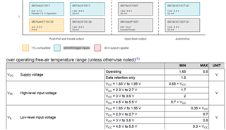
1.On the website of TI ,We can see that this buffer doesn’t feature Schmitt-trigger inputs, But the range between VIH and VIL is quite large.

Dose this buffer IC category as an Schmitt trigger? And if not , Is there any reason for this?

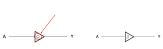
 2.Between the symbol between this buffer and other buffers feature Schmitt-trigger inputs ,It’s seems that the one with Schmitt-trigger inputs has hysteresis curve.

I’m wondering what the other symbol means in red circle at below image. Since that many people often confuse this two.

BRs

Brian

  • 1. The distance between the VIL and VIH limits does not matter. It just means that the actual switching threshold is somewhere between VIL and VIH, and that you are not allowed to apply a DC voltage in the forbidden range; it does not mean that there are two switching thresholds.

    2. The left symbol indicates an open-drain output. The right symbol indicates a Schmitt-trigger input.