TXB0104-Q1: The risk and requirement for TXB0104QRUTRQ1 in TDM application

Part Number: TXB0104-Q1
Other Parts Discussed in Thread: TAS6424E, , SN74LVC1G08, TXB0104

Tool/software:

Hi team

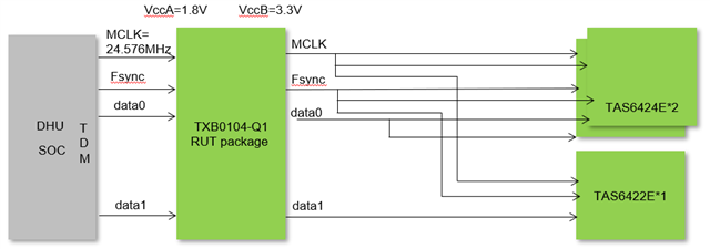
My customer will use TXB0104QRUTRQ1 in below case which is shown in block diagram. 

The requirements of TAS6424E and TAS6422E are listed

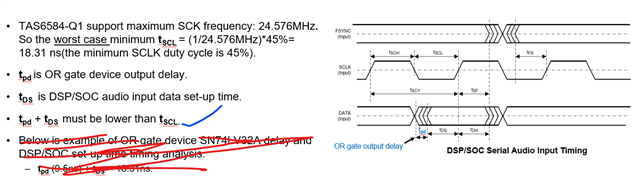
1.TAS642x has MCLK and SCLK input pins but they can be connected together.

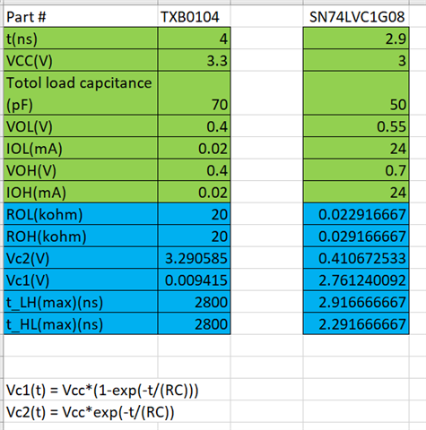
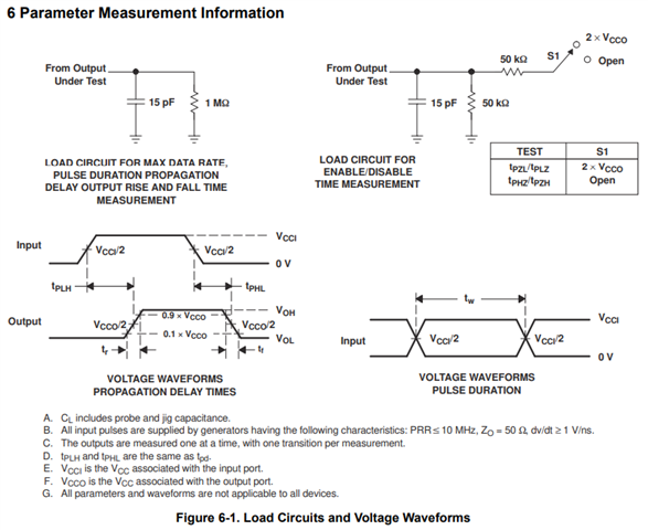
2.MCLK Trise/fall(10%-90%)  must be less than 5ns.

3.The maximum input currents are 15uA for TAS6424E’s MCLK/SCLK/Fsync/data

4.  

Would help confirm if TXB0104QRUTRQ1 is ok ? If it is ok, what's the requirements on TXB0104QRUTRQ1 and layouts?

Thanks 

  • Hi Ted,

    It appears the signals are fixed direction given the shared block diagram. As a more robust solution, the customer should consider the AXC4T774/ AVC4T774 instead.

    The rise/ fall time can then be calculated via:  [FAQ] What is the output transition rate for a logic device? 

    Regards,

    Jack

  • HI Jack

    Thanks for your comments. 

    But TXB0104-Q1 is used in customer's many project for many years. Would you help double check if it is ok and what's the requirements in this case?

    One concern is if the auto bi-direction function work well. 

    On the rise/fall time, I followed the description in your shared link and get below results. Take mentioned SN74LVC1G08 in link  as example. the maximum output transition rate is 2.9ns. seems that the calculation on txb0104 is not right that the t_LH(max)/t_HL(max) is far bigger than Vc(4ns). Would you help correct me?

    Here is the calculation tools as reference. 

    output transition rate for logic device.xlsx

    Thanks very much. 

  • Hi Ted,

    The below is the test configuration we used (15pF):

    Please note that the IOH/IOL parameter in TXB is 20uA and not in mA  like other translators. This is due to its weak drive strength, so the calculator tool is not applicable for the TXB0104 here.

    Regards,

    Jack