This thread has been locked.

If you have a related question, please click the "Ask a related question" button in the top right corner. The newly created question will be automatically linked to this question.

SN74LV161A: Output waveforms on QA-QD outputs

Part Number: SN74LV161A

Hi,

I have used this 4-bit counter for a design. I am using 2 of these. One is being clocked by a 10MHz clock and the other is being clocked by a 5MHz clock. The board design implements these as a modulo-n counter utilizing the RCO output.

I have an error on the board and I don't see the RCO pulse come back as the LOADB signal. However, the counter appears to be counting up:
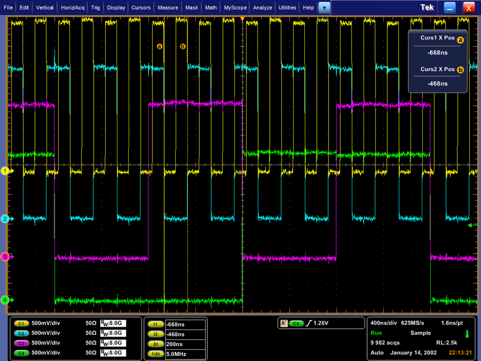
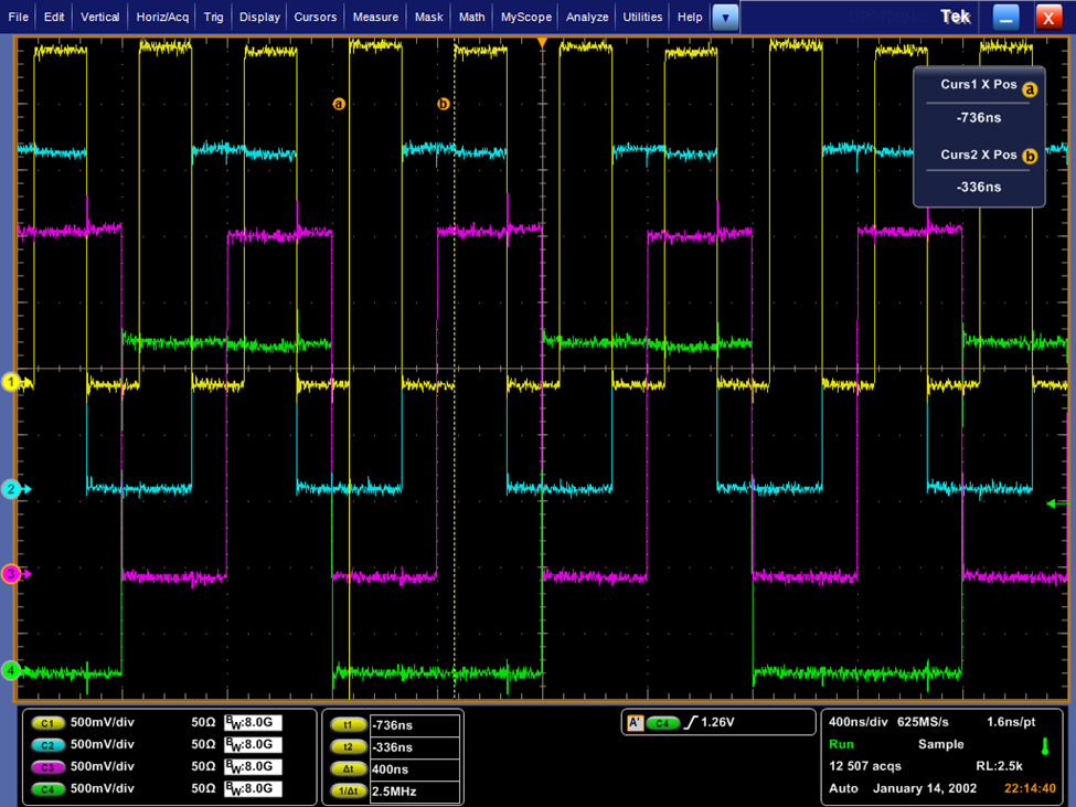
image.png

image.png

In both of the images above, yellow = QA, cyan = QB, magenta = QC and green = QD.


Both of the screen captures above show a mismatched phase of the transition on QC and QC matches QB in the 2nd one. Could this be explained by the LOADB signal being incorrect?

Thanks,

Prasoon

  • Hi Prasoon,

    It is hard to say without seeing any of the input signals. It would be useful if you could also share scope shots of the load and clock input. Also, if you adjust the scope voltages so that the output waveforms don't overlap, it would be easier for me to tell what's happening on the four outputs. 

    Best,

    Malcolm

  • Hi Malcolm,

    Here is the circuit schematic:

    RCO is being inverted by the inverter chain and fed back as loadb.

    My scope maxes out at 500mV/div. so, unfortunately the waveforms are overlapped, but, I have them stacked. Here are both counters with their respective inputs. Green: QD, Magenta: QC, Blue: QB, Yellow: Clock/RCO/Loadb. A,B,C,D are at 0'b0.

    Counter 1 (clocked @ 10MHz)

    Clock

    RCO (spikes because of placing the probe by hand)

    Loadb (measured at the counter input)

    Counter 2 (clocked @ 5MHz)

    Clock

    RCO (spikes because of placing the probe by hand)

    Loadb

    Hope that these snapshots help.

    Thanks,

    Prasoon

  • Prasoon,

    It looks like the RCO is giving off pulses. Have you checked the inverter to see if it's functioning properly?

    Best,

    Malcolm

  • Hi Malcolm,

    Checking what is wrong with the inverter is the outstanding item here.

    However, if the loadb is always high, as it looks to be in this case, can the QA-QD outputs behave like they are in the two cases above?

    Thanks,

    Prasoon

  • Hi Malcolm,

    I discovered that I have a design issue on my board. The RCO also goes to a transceiver that has been wired incorrectly (input and output swapped):

    So, there is contention on RCO from the transceiver driving 1.8V and the counter driving a 3.3V pulse. This is the most likely reason why the output of the inverter is stuck high.

    How do we explain the transitions on QA-QD bus at the negative clock edge ? As per the data sheet LOADB is not involved with the clock path.

    Prasoon

  • Hi Prasoon, 

    With respect to American Thanksgiving we will respond to this on Monday 

    -Owen

  • Hi Prasoon,

    Are you able to zoom in on your clock edges, both rising and falling edge?

    Best,

    Malcolm

  • Hi Malcolm,

    Please have a look at this zoomed in image below for the counter clocked by the 5MHz clock:

    D:A = 4’b0

    G: QD, M: QC, B: QB, Y: Clk

    Regards,

    Prasoon

  • Hi Prasoon,

    I meant a detailed look at the clock edges to see what the quality of the signal looks like on the falling edge, to see if there is some sort of noise step halfway through that could be causing an erroneous trigger.

    From what I can tell, your 10MHz clocked counter does not have this problem. Are these devices physically close to one another on your board? I am wondering if the rising edge from the 10MHz counter is coupling noise with the falling edge from the 5MHz counter and causing the trigger. Maybe you could try turning off or removing the 10MHz clock.

    Best,

    Malcolm