This thread has been locked.

If you have a related question, please click the "Ask a related question" button in the top right corner. The newly created question will be automatically linked to this question.

TXB0108: TXB0108 Input / Output Direction Detection

Part Number: TXB0108
Other Parts Discussed in Thread: TXS0108E

Hello,

Previously with a different TXB level translators many years back we found a problem was with the direction detection / definition of the pins during initialization.
During initialization of the pins and the inputs to the device are undefined.
At this stage, the pins assumed directions by themselves and sometimes get stuck even when pins are configured.
We had to pull up and pull down all the inputs to the level translator just to make sure it worked as intended by us.

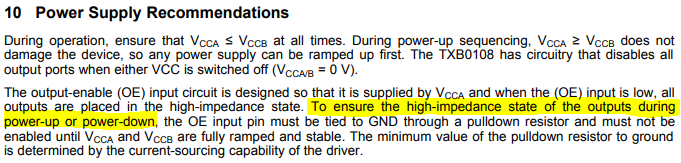
In the datasheet it mentions that the OE signal should be pulled down and should be enabled only after VCCA and VCCB are both stable.  (This seems similar to TXS devices.)
Could we use an RC to delay it slightly to solve this problem?

Thanks very much, Keith

  • Hello Keith,

    The TXB level translator shouldn't be used with pull-up or pull-down resistors because of its internal structure.  You are correct that the pins are undefined at startup -- they could start high or low - the TXB is essentially configured as a weak latch:

    This schematic shows a very simplified view of the TXB device's internals. Bn is driven by the lower buffer which is controlled by the voltage at An, and An is driven by the upper buffer which is controlled by the voltage at Bn.  If left alone, this system will latch to either high or low. At startup, the only way to be absolutely certain of the state is to force one side into a known state.

    Adding a pull-up or pull-down resistor to An or Bn would result in a voltage divider and a number of problems. We highly recommend against this solution.

    The OE pin should only be pulled down if you want to ensure that the device starts in the high-impedance state. Otherwise it can be tied high or connected to a controller directly.

    I would recommend against connecting a standard CMOS input directly to an RC. This will result in excessive current in the input, and can cause oscillations, unexpected behavior, and damage. There's a great applications report on this topic here: Implications of Slow or Floating CMOS Inputs

    If you need a power on reset signal, I would recommend following the suggestions in this short video: Generate a Reset Signal at System Power On

  • Hello,

    Is it safe to say that the TXS0108E (or TXS series in general) would not have this “issue”, since it has internal pull-ups?
    Or, perhaps direction is defined by power up sequencing (VCCA then VCCB, etc.) in that case?

    Regarding the RC circuit: could this be used on the OE pin to cause the I/O pins to remain Hi-Z on power up, until both VCC pins are stable?

    Thank you, Keith
  • Hey Keith,
    TXS translators are essentially passive switch translators with some added bells and whistles - they (essentially) work the same way that the LSF family does - there's a great Logic Minute video series on that.

    If the "issue" you're talking about is starting in an unknown state - then yes, TXS will always start in the 'high' state if nothing is connected to it, because of the internal pull-up resistors. There are other design concerns around TXS or LSF -- there's no "free lunch" in auto-bidirectional translation.

    Regarding the RC circuit - I would recommend against connecting a standard CMOS input directly to an RC (ie the OE input). This will result in excessive current in the input, and can cause oscillations, unexpected behavior, and damage. There's a great applications report on this topic that I linked above.

    If you need a power on reset signal, I would recommend following the suggestions in the video I also linked above.