
- Ask a related questionWhat is a related question?A related question is a question created from another question. When the related question is created, it will be automatically linked to the original question.
Hi Team,
This Bus Transceiver is used to perform level conversion from 1.2V to 1.8V.
The signal direction is fixed at the DIR terminal, and is 1.2 V input and 1.8 V output.
Attach 1.2V input (waveform 1) and 1.8V output (waveform 2)
At this time, the output waveform does not swing from 0 V to 1.8 V.
The output is measured by connecting only a 500 MHz band oscilloscope.
What causes the output not to swing?
In addition, the data sheet has the following description.
"Up to 380 Mbps Support When Translating from 1.8 V to 3.3 V"
How many can be supported when converting from 1.2V to 1.8V?
waveform 1
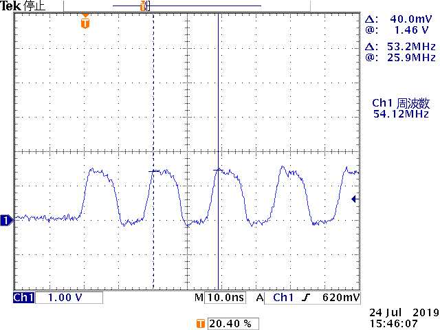
waveform 2

Best Regards,


