This thread has been locked.

If you have a related question, please click the "Ask a related question" button in the top right corner. The newly created question will be automatically linked to this question.

SN74HC595: Realized flow lamp

Part Number: SN74HC595

Dear all:

      I want to use the following circuit to achieve the flow light control

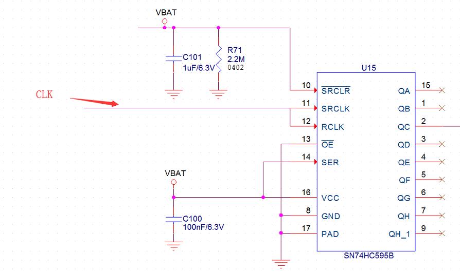
Now, however, once the CLK is triggered, the output is all high

Did I make any mistakes?Can you give me some advice to realize the water lamp control?

Thank you!

  • I want to use the following circuit to achieve the flow light control

  • Hello,

    I'm afraid I don't know what a "water lamp control" or a "flow light control" is. It's probably not important to the logic circuit though.

    You must first clear the registers in the device before starting operation. There's a video that shows how to make a power-on-reset pulse located here:

    https://training.ti.com/tlm-app-por?cu=1134826


    There's also an FAQ about the default starting state of a latched device:

    [FAQ] What is the default output of a latched device? (Flip-Flop, latch, register) - Logic forum - Logic...

    e2e.ti.com
    FAQ: Logic and Voltage Translation > Output Parameters >> Current FAQ Flip-flops, latches, and registers do not have a default state on power up. The output is
     

    Once the device is properly initialized, and assuming tha tyou have RCLK and SRCLK tied together (there is no junction dot to indicate a connection in your schematic), then every clock pulse after the first will cause the output to increment until the next reset pulse.

    Please let me know if I can be of further assistance.