This thread has been locked.

If you have a related question, please click the "Ask a related question" button in the top right corner. The newly created question will be automatically linked to this question.

TMS570LC4357: UART bootloader in TMDX570LC43HDK

Part Number: TMS570LC4357
Other Parts Discussed in Thread: TMDX570LC43HDK, HALCOGEN, , TMS570LS1224

Hi Team, 

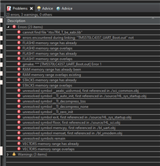
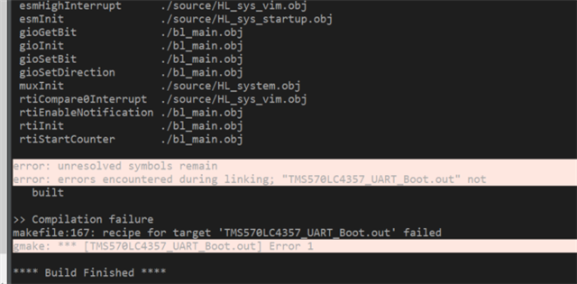
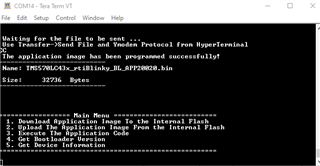
UART Bootloader for Hercules is TMS570LS12x MCU  need to support for TMDX570LC43HDK 

http://www.ti.com/lit/zip/spna192

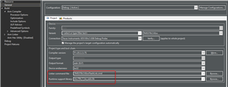
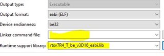
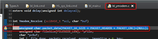
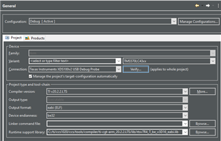
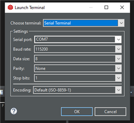
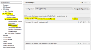
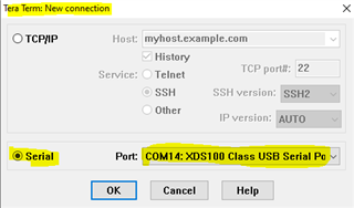
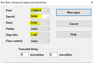
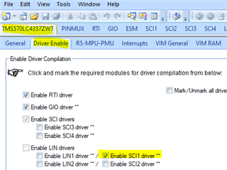
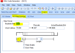
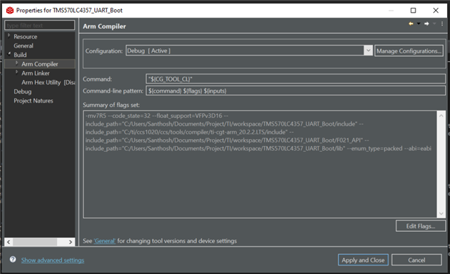
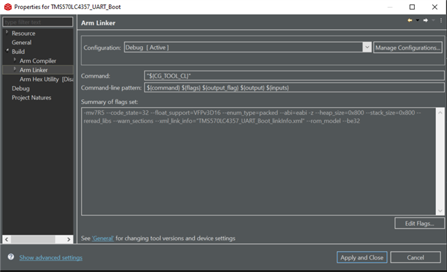
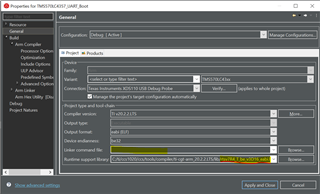
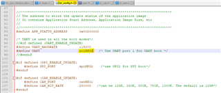
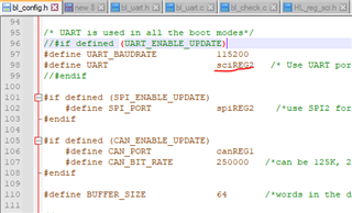
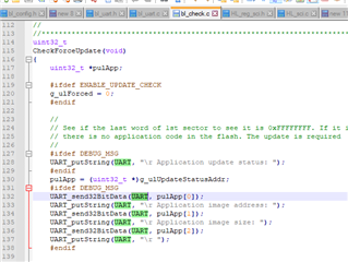
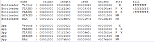
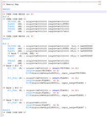
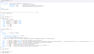
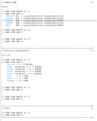
How to configure the Hercules TMDX570LC43HDK  in HALCoGen   for UART bootloader and what all the modification need to do in code?

  • I have checked the forum and got this UART bootloader code for LC43x which is given in forum 

    "

    Enclosed is an UART bootloader example on TMS570LC43x device. The bootloader is programmed in the 1st flash sector, and the application is programmed at the 1st sector of bank1. It is just an example.

    TMS570LC4357_UART_Boot.7z "

    Using this I have got an error 

    support me to debug this error.

    Please confirm me the linker commend file and Runtime support library ?

  • Hi Santhosh,

    I posted an example of LC43x UART bootload to this forum before. I will find the link for you later.

  • Please use the run-time library highlighted in my screenshot. This library supports floating-point. 

    Don't use the default linker cmd file. The project has its own linker cmd file.

  • Hi QJ Wang,

    Now the LC43x UART bootloader project is complied but I didn't get any response in UART terminal 

    warning need to check ?

    Confirm this warning and the Terminal i couldn't see any information .

    Please support me to debug the code.

  • There may be several serial ports available in your terminal. The port with xds100v2 Application should be used.

    The baudrate on both side (terminal, and TMS570) should match each other.

  • Hi QJ Wang,

    Yes I have using the same port xds100v2 (COM7) But still I get any message in COM7 terminal

    Can you please guide me on this.

    I couldn't see the HL_SCI.h driver file for UART instead of this driver. Is it 

    sci_common.h is used. Can you show me the HALCoGen driver setting? 

    How Can I share the full build in this chat ?

    Thanks in advance 

    Santhosh

  • Hi QJ Wang

    Help me to resolve this 3 warning .

    Thank you

  • HI QJ Wang

    I have used your build which you have shared but I have face this issue 

    Please help me in this debug.

    I have used the old TS1224 board this code is working but I couldn't use the TC43x HDK board for do the same.

    Thank you

  • HI QJ Wang

    removed NULL declaration.

    I have solved the above 3 warning 

    Please confirm why this flash verification is failed while running the debug.

  • The ECC is generated using Linker CMD file. You need to uncheck "ECC Auto Generation" and "Verification" when loading code to flash.

  • Hi QJ Wang,

    Yes, I have selected None for Flash verification settings. the project is executed now

    but I couldn't see the result in com7 

    Previously I have used LS1224 UART bootloader which is worked But in LC43x it is not working 

    What is the main reason of this issue ?

  • The LS1224 UART bootloader doesn't use ECC from Linker.

    BTW, if you use new version CCS, you need to enable the Linker ECC manually in linker property:

  • Still I couldn't see the UART messages in COM7 

    Can you share me the working project for LC43x in HDK board?

  • This is an example project for LED blinky and SCI display.

    TMS570LC43x_rtIBlinky.zip

  • Hi QJ Wang,

    I have tested the TMS570LC43x_rtIBlinky.zip. It is working perfectly in the HDK board. 

    I know that this code will work because I already tested the UART code. 

    I have doubt in configuration of the build for UART bootloader is not available for edit HALCoGen setup in UART build. 

    So can you provide me the build or how can I attach the build here in this forum ?

  • Hi QJ Wang,

    Can you test the code in HDK with latest CCS TI v20.2.2.LTS. 

    Please confirm this error 

  • The example code of UART bootloader I posted should work. I tested the example code, it can display the debug information.

  • HI QJ Wang,

    Now I have tried to use the UART bootloader in TMS570LC43x board Launchpad now. 

    without Linker command file 

    no error in build. we could execute or debug it. 

    But If I add the HL_sys_link command file then I am getting this error in build compiler

    Can you check it and confirm what is the issue in this ?

    Warm regards,

    Santhosh

  • Hi QJ Wang,

    Did I need to modify the command file for linker ?

    /* */
    /*----------------------------------------------------------------------------*/
    /* USER CODE BEGIN (0) */
    /* USER CODE END */


    /*----------------------------------------------------------------------------*/
    /* Linker Settings */

    --retain="*(.intvecs)"

    /* USER CODE BEGIN (1) */
    /* USER CODE END */

    /*----------------------------------------------------------------------------*/
    /* Memory Map */

    MEMORY
    {
    /* USER CODE BEGIN (2) */
    /* USER CODE END */
    VECTORS (X) : origin=0x00000000 length=0x00000020
    FLASH0 (RX) : origin=0x00000020 length=0x001FFFE0
    FLASH1 (RX) : origin=0x00200000 length=0x00200000
    STACKS (RW) : origin=0x08000000 length=0x00001500
    RAM (RW) : origin=0x08001500 length=0x0007EB00

    /* USER CODE BEGIN (3) */
    /* Bank 0 ECC */
    /*
    ECC_VEC (R) : origin=(0xf0400000 + (start(VECTORS) >> 3))
    length=(size(VECTORS) >> 3)
    ECC={algorithm=algoL2R5F021, input_range=VECTORS}

    ECC_FLA0 (R) : origin=(0xf0400000 + (start(FLASH0) >> 3))
    length=(size(FLASH0) >> 3)
    ECC={algorithm=algoL2R5F021, input_range=FLASH0 }
    */
    /* Bank 1 ECC */
    /* ECC_FLA1 (R) : origin=(0xf0400000 + (start(FLASH1) >> 3))
    length=(size(FLASH1) >> 3)
    ECC={algorithm=algoL2R5F021, input_range=FLASH1 }
    */
    /* USER CODE END */
    }

    /* USER CODE BEGIN (4) */
    //ECC {
    // algoL2R5F021 : address_mask = 0xfffffff8 /* Address Bits 31:3 */
    // hamming_mask = R4 /* Use R4/R5 build in Mask */
    // parity_mask = 0x0c /* Set which ECC bits are Even and Odd parity */
    // mirroring = F021 /* RM57Lx and TMS570LCx are build in F021 */
    //}

    /* USER CODE END */


    /*----------------------------------------------------------------------------*/
    /* Section Configuration */

    SECTIONS
    {
    /* USER CODE BEGIN (5) */
    /* USER CODE END */
    .intvecs : {} > VECTORS
    .text align(32) : {} > FLASH0 | FLASH1
    .const align(32) : {} > FLASH0 | FLASH1
    .cinit align(32) : {} > FLASH0 | FLASH1
    .pinit align(32) : {} > FLASH0 | FLASH1
    .bss : {} > RAM
    .data : {} > RAM
    .sysmem : {} > RAM

    /* USER CODE BEGIN (6) */

    /* USER CODE END */
    }

    /* USER CODE BEGIN (7) */
    /* USER CODE END */


    /*----------------------------------------------------------------------------*/
    /* Misc */

    /* USER CODE BEGIN (8) */
    /* USER CODE END */
    /*----------------------------------------------------------------------------*/

    Please check and confirm did I need to modify it ?

  • The error message indicates that two linker cmd files are in your project.

  • Hi QJ Wang,

    Now I am getting this error while debug. but if I execute any other project It is working fine.

    Please let me know the issue in this UART bootloader code.

    Thank you in advance.

  • I did a test using this bootloader, it works without any issue. 

    What is the debug errors? 

    From your snapshot, the COM6 should be used.

  • Hi QJ Wang,

    Can you confirm is it the memory issue ?

    I am using Launchpad or HDK TMS570LC43x.  

    XDS110 USB Debug Probe/CortexR5 is suspended. 

    Thank you in advance.

  • Hi QJ Wang,

    Finally, I got some results in UART bootloader. because the configuration is 9600 for UART but it in TMS570LS1224 it is 11500 


    Still I am having a issue in Download Application Image to the Internal Flash 

    The packet is not running and  getting No response from remote system.

    Please provide me the solution and HALCoGen package for the same project 

    Thank you 

    Santhosh

  • try this, just tested without any issue. The HAL configuaration file is in HALCOGen folder:

    TMS570LC4357_UART_BootLoader.zip

  • Hi QJ Wang,

    I am getting this below issue in debug mode.

    the new code TMS570LC4357_UART_BootLoader.zip is compiled fine but had issue in debug mode.

    Please confirm why the debugger is not connecting ?

    Thank you 

  • Hi QJ Wang,

    The new code is working with the TMS570LC4357 Launchpad but it is not working in HDK board

  • It works on HDK without any issue.

  • Hi QJ Wang,

    I need a support in UART bootloader in SCI2 instead of SCI1 driver.

    So I have to change the UART configuration for SCI2 in HalCoGen and in code. 

    I have changed only in config.h file UART as sciREG2 from sciREG1

    Please confirm me any other changes need to do for SCI1 to SCI2. 

    Thank you.

  • Hello,

    Yes, change of the UART definition in bl_config.h is required.

    BTW, on HDK, there is no UART transceiver for SCI2.

  • Yes both are same circuit. 

    I have changed the code in two places,

    1. 

    2.

    Please confirm me the SCI1 is worked in both Launchpad and as well as in our custom board . 

    same code is not working with the SCI2 in both Launchpad and our board. 

    basic UART is working in both the SCI1 and SCI2 in both launchpad and our custom board.

    Thank you 

  • There is no UART transceiver for SCI2 on HDK and launchpad. How did you make SCI2 to communicate with PC terminal?

  • Yes, But I have used a external UART transceiver for SCI2 it is working now in Launchpad of LC43x. Bootloader also working fine in SCI2 .

    The issue I have faced is the blinking application bin file is used while debug mode it is working but it is working the non debug mode LED is ON but it is not blinking. Thank you for your support.

  • Hi QJ Wang,

    I have a few Issues in UART bootloader after loaded Application code in it.

    1. Jumping application code works fine after when application code (LED blinking) wrote into flash in debug mode. But after first nRST or PORRST the from bootloader it enters application code but LED blinking is not working because of reset source is NO_RESET.

    2.  _c_int00() functions are there in both UART bootloader and my application code it is same. Did I need to configurate the HALCoGen for the UART bootloader and application should be same or different. 

    3. HL_sys_link.cmd file in UART bootloader and Application code 

    Bootloader sys_intvecs.asm:

    resetEntry
                       b _c_int00
    undefEntry
                      b undefEntry

                      b 0x2000F8  ;0x200100-0x8   for svc

    Application sys_intvecs.asm:

    resetEntry
                       b _c_int00
    undefEntry
                      b undefEntry

                      b vPortSWI

    4. Which all the files need to modify in UART bootloader and application code?

    Please help in this section.

  • Hi QJ Wang

    Did I need to modify the HL_sys_intvecs.asm file and how because both the UART bootloader and Application code is in same.


    .sect ".intvecs"
    .arm

    ;-------------------------------------------------------------------------------
    ; import reference for interrupt routines

    .ref _c_int00
    .ref phantomInterrupt
    .def resetEntry

    ;-------------------------------------------------------------------------------
    ; interrupt vectors

    resetEntry
                 b _c_int00
    undefEntry
                 b undefEntry
    svcEntry
                 b svcEntry
    prefetchEntry
                 b prefetchEntry
    dataEntry
                 b dataEntry
                 b phantomInterrupt
                 ldr pc,[pc,#-0x1b0]
                 ldr pc,[pc,#-0x1b0]

    HL_sys_link.cmd file what all I need to change in Bootloader and Application code both usage is in FLASH0 

    HL_sys_link.cmd file -- application

    /*----------------------------------------------------------------------------*/
    /* USER CODE BEGIN (0) */
    /* USER CODE END */


    /*----------------------------------------------------------------------------*/
    /* Linker Settings */

    --retain="*(.intvecs)"

    /* USER CODE BEGIN (1) */
    /* USER CODE END */

    /*----------------------------------------------------------------------------*/
    /* Memory Map */

    MEMORY
    {
    /* USER CODE BEGIN (2) */
    /* USER CODE END */
    VECTORS (X) : origin=0x00000000 length=0x00000020
    FLASH0 (RX) : origin=0x00000020 length=0x001FFFE0
    FLASH1 (RX) : origin=0x00200000 length=0x00200000
    STACKS (RW) : origin=0x08000000 length=0x00001500
    RAM (RW) : origin=0x08001500 length=0x0007EB00

    /* USER CODE BEGIN (3) */
    /* USER CODE END */
    }

    /* USER CODE BEGIN (4) */
    /* USER CODE END */


    /*----------------------------------------------------------------------------*/
    /* Section Configuration */

    SECTIONS
    {
    /* USER CODE BEGIN (5) */
    /* USER CODE END */
    .intvecs : {} > VECTORS
    .text align(32) : {} > FLASH0 | FLASH1
    .const align(32) : {} > FLASH0 | FLASH1
    .cinit align(32) : {} > FLASH0 | FLASH1
    .pinit align(32) : {} > FLASH0 | FLASH1
    .bss : {} > RAM
    .data : {} > RAM
    .sysmem : {} > RAM

    /* USER CODE BEGIN (6) */
    /* USER CODE END */
    }

    LC43xLEDBlk.map -- Application code

    ******************************************************************************
    TI ARM Linker PC v20.2.2
    ******************************************************************************
    >> Linked Tue Jun 15 12:27:39 2021

    OUTPUT FILE NAME: <LC43xLEDBlk.out>
    ENTRY POINT SYMBOL: "_c_int00" address: 000045ac


    MEMORY CONFIGURATION

    name origin length used unused attr fill
    ---------------------- -------- --------- -------- -------- ---- --------
    VECTORS 00000000 00000020 00000020 00000000 X
    FLASH0 00000020 001fffe0 00004e10 001fb1d0 R X
    FLASH1 00200000 00200000 00000000 00200000 R X
    STACKS 08000000 00001500 00000000 00001500 RW
    RAM 08001500 0007eb00 00000000 0007eb00 RW


    SEGMENT ALLOCATION MAP

    run origin load origin length init length attrs members
    ---------- ----------- ---------- ----------- ----- -------
    00000000 00000000 00004870 00004870 r-x
    00000000 00000000 00000020 00000020 r-x .intvecs
    00000020 00000020 00004850 00004850 r-x .text
    00004880 00004880 000005c0 000005c0 r--
    00004880 00004880 000005c0 000005c0 r-- .const

    Similarly in UART bootloader is 

    HL_sys_link.cmd file -- bootloader

    /* */
    /*----------------------------------------------------------------------------*/
    /* USER CODE BEGIN (0) */
    /* USER CODE END */


    /*----------------------------------------------------------------------------*/
    /* Linker Settings */

    --retain="*(.intvecs)"

    /* USER CODE BEGIN (1) */
    /* USER CODE END */

    /*----------------------------------------------------------------------------*/
    /* Memory Map */

    MEMORY
    {
    /* USER CODE BEGIN (2) */
    #if 0
    /* USER CODE END */
    VECTORS (X) : origin=0x00000000 length=0x00000020
    FLASH0 (RX) : origin=0x00000020 length=0x001FFFE0
    FLASH1 (RX) : origin=0x00200000 length=0x00200000
    STACKS (RW) : origin=0x08000000 length=0x00001500
    RAM (RW) : origin=0x08001500 length=0x0007eb00

    /* USER CODE BEGIN (3) */
    #endif

    #if 1
    VECTORS (X) : origin=0x00000000 length=0x00000020 fill = 0xffffffff
    FLASH0 (RX) : origin=0x00000020 length=0x001FFFE0 vfill = 0xffffffff
    FLASH1 (RX) : origin=0x00200000 length=0x00200000 vfill = 0xffffffff
    /* Bank 7 (128kB, FEE) */
    FLASH7 (R) : origin=0xF0200000 length=0x00020000 vfill = 0xffffffff

    STACKS (RW) : origin=0x08000000 length=0x00001500
    RAM (RW) : origin=0x08001500 length=0x0002EB00
    /* Bank 0 ECC */
    ECC_VEC (R) : origin=(0xf0400000 + (start(VECTORS) >> 3))
    length=(size(VECTORS) >> 3)
    ECC={algorithm=algoL2R5F021, input_range=VECTORS}

    ECC_FLA0 (R) : origin=(0xf0400000 + (start(FLASH0) >> 3))
    length=(size(FLASH0) >> 3)
    ECC={algorithm=algoL2R5F021, input_range=FLASH0 }

    /* Bank 1 ECC */
    ECC_FLA1 (R) : origin=(0xf0400000 + (start(FLASH1) >> 3))
    length=(size(FLASH1) >> 3)
    ECC={algorithm=algoL2R5F021, input_range=FLASH1 }

    /* Bank 7 ECC */
    ECC_FLA7 (R) : origin=0xF0100000
    length=(size(FLASH7) >> 3)
    ECC={algorithm=algoL2R5F021, input_range=FLASH7 }
    #endif
    /* USER CODE END */
    }

    /* USER CODE BEGIN (4) */
    #if 1
    ECC {
    algoL2R5F021 : address_mask = 0xfffffff8 /* Address Bits 31:3 */
    hamming_mask = R4 /* Use R4/R5 build in Mask */
    parity_mask = 0x0c /* Set which ECC bits are Even and Odd parity */
    mirroring = F021 /* RM57Lx and TMS570LCx are build in F021 */
    }
    #endif
    /* USER CODE END */


    /*----------------------------------------------------------------------------*/
    /* Section Configuration */

    SECTIONS
    {
    /* USER CODE BEGIN (5) */
    #if 0
    /* USER CODE END */
    .intvecs : {} > VECTORS
    .text align(32) : {} > FLASH0 | FLASH1
    .const align(32) : {} > FLASH0 | FLASH1
    .cinit align(32) : {} > FLASH0 | FLASH1
    .pinit align(32) : {} > FLASH0 | FLASH1
    .bss : {} > RAM
    .data : {} > RAM
    .sysmem : {} > RAM

    /* USER CODE BEGIN (6) */
    #endif

    #if 1
    .intvecs : {} palign=8 > VECTORS
    flashAPI:
    {
    .\Boot\Fapi_UserDefinedFunctions.obj (.text)
    .\Boot\bl_flash.obj (.text)
    --library = F021_API_CortexR4_BE_L2FMC.lib (.text)
    } palign=8 load = FLASH0 |FLASH1, run = RAM, LOAD_START(apiLoadStart), RUN_START(apiRunStart), SIZE(apiLoadSize)

    .text : {} palign=8 > FLASH0 |FLASH1 /*Initialized executable code and constants*/
    .const : {} palign=8 load=FLASH0 |FLASH1, run = RAM, LOAD_START(constLoadStart), RUN_START(constRunStart), SIZE(constLoadSize) /*Initialized constant data (e.g. const flash_sectors[..] = )*/
    .cinit : {} palign=8 > FLASH0 | FLASH1 /* Tables for explicitly initialized global and static variables */
    .pinit : {} palign=8 > FLASH0 | FLASH1 /* C++ global constructor addresses */
    .bss : {} > RAM /* Uninitialized global and static variables */
    .data : {} > RAM /* Global and static non-const variables that are explicitly initialized. */
    .sysmem : {} > RAM /* Memory pool (heap) for dynamic memory allocation */
    #endif

    /* USER CODE END */
    }

    /* USER CODE BEGIN (7) */
    /* USER CODE END */

    TMS570LC4357_UART_BootLoader.map -- bootloader

    ******************************************************************************
    TI ARM Linker PC v20.2.2
    ******************************************************************************
    >> Linked Tue Jun 15 13:11:25 2021

    OUTPUT FILE NAME: <TMS570LC4357_UART_BootLoader.out>
    ENTRY POINT SYMBOL: "_c_int00" address: 00008abc


    MEMORY CONFIGURATION

    name origin length used unused attr fill
    ---------------------- -------- --------- -------- -------- ---- --------
    VECTORS 00000000 00000020 00000020 00000000 X ffffffff
    FLASH0 00000020 001fffe0 00009378 001f6c68 R X (ffffffff)
    FLASH1 00200000 00200000 00000000 00200000 R X (ffffffff)
    STACKS 08000000 00001500 00000000 00001500 RW
    RAM 08001500 0002eb00 0000197b 0002d185 RW
    ECC_FLA7 f0100000 00004000 00000000 00004000 R
    FLASH7 f0200000 00020000 00000000 00020000 R (ffffffff)
    ECC_VEC f0400000 00000004 00000000 00000004 R
    ECC_FLA0 f0400004 0003fffc 00000000 0003fffc R
    ECC_FLA1 f0440000 00040000 00000000 00040000 R


    SEGMENT ALLOCATION MAP

    run origin load origin length init length attrs members
    ---------- ----------- ---------- ----------- ----- -------
    00000000 00000000 00000020 00000020 r-x
    00000000 00000000 00000020 00000020 r-x .intvecs
    00001498 00001498 00007f00 00007f00 r-x
    00001498 00001498 00007ec0 00007ec0 r-x .text
    00009358 00009358 00000040 00000040 r-- .cinit
    08001500 00000020 00001478 00001478 r-x
    08001500 00000020 00000ef0 00000ef0 r-x flashAPI
    080023f0 00000f10 00000588 00000588 r-- .const
    08002978 08002978 00000506 00000000 rw-
    08002978 08002978 00000439 00000000 rw- .data
    08002db4 08002db4 000000ca 00000000 rw- .bss

  • The Bootloader and Application should not use the same the same linker cmd file. In The memory address for VECTROS and FLASH are different.

    Bootloader:  

       MEMORY:

               VECTORS (X) : origin=0x00000000 length=0x00000020

               FLASH0 (RX) : origin=0x00000020 length=0x001FFFE0

               FLASH1 (RX) : origin=0x00200000 length=0x00200000

    Application:  

           MEMORY:

               VECTORS (X) : origin=0x00200000 length=0x00000020

               FLASH0 (RX) : origin=0x00000000 length=0x00200000

               FLASH1 (RX) : origin=0x00200020 length=0x001FFFE0

          REGIONS:

              .intvecs : {} > VECTORS
              .text align(32) : {} >  FLASH1
              .const align(32) : {} > FLASH1
              .cinit align(32) : {} >  FLASH1
              .pinit align(32) : {} >  FLASH1

  • If you use the same interrupt vector table (.intvecs), it will work fine if no exception (data abort, prefetch, etc) occurs in your application). Since the bootloader is used for updating the application only, it is concise. I assume the bootloader is bug-free. In my bootloader examples, all the exceptions (undef, prefetch, data about, svc) are routed to Application. 

    Bootloader sys_intvecs.asm:

    resetEntry
                       b _c_int00

                      b 0x2000FB  ;undef

                      b 0x2000F8  ;0x200100-0x8   for svc

                      b 0x2000FB  ;prefetch

                      b 0x2000FB  ;data abort


  • Hi QJ Wang,

    I have checked after updated the linker cmd file, Then the application is working fine now.

  • If the problem has been resolved, please click "Resolved" button. Thanks

  • Yes. I have no issue in Launchpad of TMS570LC4357 but in our customised MCU board has issue of after the hardware RESET the application code is not booting properly. What is the reason only in customised MCU board. 

  • HI QJ Wang

    How to use Stack and RAM memory allocation of Bootloader and application 

    Bootloader

    Application 

    Please can you confirm about the stack, RAM and ECC.

  • The stack size of 0x1500 should be fine for your simple application example (led blinky). What do you mean by "application code is not booting properly"? Does the execution jump to application code? Are the programs (bootloader and application) exactly same as used on TI Launchpad? Is there any error flag set in ESM status registers? 

  • Hi QJ Wang,

    In Launchpad the execution jump from bootloader to application (LED Blinky) is perfect, But in our custom board  the application (LED Blinky) is working when the debug mode is connected once we RESET then the application LED Blinky is not working. 

    How to check the ESM status register? 

  • @QJwang - I can get the UART bootloader to run, I'm able to upload an application, but the option to run the application hangs. 

    I uploaded the blinky sample (FREERTOS or RTI version) by itself and both work. But uploading via the Bootloader and executing it via the menu (option 3) -- it hangs.

    I had an older (incorrect?) version of the bootloader with different addresses.

    APP_START_ADDRESS       0x00010020
    APP_STATUS_ADDRESS       0x00010000

    The version from this forum post:

    APP_START_ADDRESS 0x00200020
    APP_STATUS_ADDRESS 0x00200000

    The Hercules HDK PDF (spnu597a page 7) has a memory map that doesn't show the same addresses for either.

  • The application can be loaded to any sectors of the flash. 0x10000 is the start address of sector 4 of Bank 0, and 0x200000 is the start address of sector 0 of Bank 1. 

  • I added the command line post-build to build a .bin file, uploaded it -- still won't start.

    What changes in the application (if any) are required to be compatible with the bootloader?

    Note: I used the bootloader you posted in this thread with 1 change - the UART is set to SCI3 - are there any issues with using SCI3? The menu comes up, I can upload and everything works except for running the app.

    Attaching the bootloader and application projects.   BootloaderProjects.zip

  • How is the link file setup for the TMS570LC43x_rtiBlinky_BL_APP200020 project?

  • The application example I posted should be programmed to 0x20020. Here is the linker file. I will post the whole project for you.

    5086.HL_sys_link.cmd