This thread has been locked.

If you have a related question, please click the "Ask a related question" button in the top right corner. The newly created question will be automatically linked to this question.

TMS570LS3137: (SCI communication) Missing data when using sciReceive function.

Part Number: TMS570LS3137
Other Parts Discussed in Thread: TMDS570LS31HDK

Hi,

I have two Hercules TMDS570LS31HDK Launchpad. My main goal is receiving data from Hercules 1 in Hercules 2. 
Our data looks like Fig.1.


Fig.1. Sending Data (Correct)


Fig.2. Receiving Data (Incorrect)

I do not observe any problems while sending the data, but when I want to receive the data with Hercules 2, I noticed that some bytes are missing. (Seen in Fig.2.)
My experimental setup is as follows: When the GIOA7 button on Hercules 1 is pressed, data is sent from Hercules 1 to Hercules 2. Hercules 2 runs the code in the code snippet below.


Fullscreen
1
2
3
4
5
6
7
8
9
10
11
12
13
14
15
16
17
18
19
uint8 packageData[100];
uint32 receivingSecondByteData;
int byteNo;
while(1){
receivingSecondByteData = 0;
byteNo = 0;
while(receivingSecondByteData != 0x16)
{
receivingSecondByteData = sciReceiveByte(scilinREG);
packageData[byteNo] = receivingSecondByteData;
byteNo++;
}
for(int i=0; i< 10000000; i++){}
if(byteNo != 0){
vSciDisplayText(scilinREG, &packageData[0], byteNo);
}
for(int i=0; i< 10000000; i++){}
}
XXXXXXXXXXXXXXXXXXXXXXXXXXXXXXXXXXXXXXXXXXXXXXXXXX


I don't understand why I am not getting the data properly. 

Thanks for help, Regards.

  • Hello,

    On HDK, the SCI2 (scilin) signals are routed to min-usb port. The SCI is a point to point communication, so would you please use SCI for two boards communication?

    You can use interrupt mode for receiving data instead of polling mode.

  • Thanks for solution. But I am not understand very well about min-usb port issue. Why I am missing some value because of scilin signals are routed to min-usb port? 

  • Hi Cevdet,

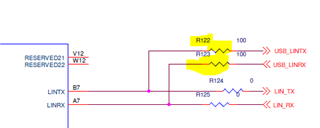
    I guess you connect HDK1 J11-pin 5  to the HDK2 J11-pin 6, and HDK1 J11-pin 6 to HDK2 J11-pin5.

    On HDK board, the SCI signals are routed to FTDI chip (UART--USB) and connector J11. I don't think the SCI can drive two devices: FTDI and HDK2 SCI.

    Would you try to remove the resistor R122 and R123 for your test? R122 and R123 are located on the backside of HDK.