This thread has been locked.

If you have a related question, please click the "Ask a related question" button in the top right corner. The newly created question will be automatically linked to this question.

TM4C1294KCPDT: Ethernet for 100mbps is not working.

Part Number: TM4C1294KCPDT
Other Parts Discussed in Thread: TPS2379

We have made our custom board using TM4c1294KCPDT controller. Modbus Ethernet communication is working ok with Eval Kit with speed 100Mbps.

We have assembled 10 number of boards, 4 number of custom boards are working OK with 100Mbps speed but 6 boards are not working with 100Mbps speecd they are working with 10Mbps speed.

We have used RJ45 connector with internal coil.

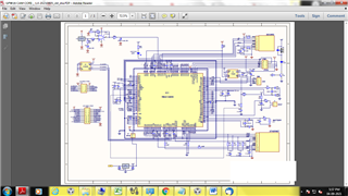
Please check the attached circuit diagram for ethernet connection.

Please guide us , if there is some hardware software improvement required
  • Hi,

      First of all, your screenshot is really hard to see the detail. In the future, you should attach PDF.  From a high level, I don't see a protection diode between the MCU and the RJ45. Without the protection diode the MCU can be damaged only partially working in a working-wounded state. Below is one TI reference design that has the RJ45 with built-in transformer. Note the protection in between the MCU and RJ45. The protection diode is also shown in device datasheet and TM4C129 system design guideline. 

    Reference TI at https://www.ti.com/tool/TIDM-TM4C129POEAUDIO.

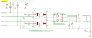
    Below is the schematic portion with respect to Ethernet connnection.

    TIDM_TM4C129POE-Schematic.pdf

    Here is the link tot he system design guideline. https://www.ti.com/lit/pdf/spma056

  • In our design we have not used the protection. Is that the reason it is not working with 100Mbps Ethernet.

    We have earlier developed one product last year, which has same design it works on one go

    Please check the attached document.

    we refer spma056 while designing the board.

  • In our design we have not used the protection. Is that the reason it is not working with 100Mbps Ethernet.

    We have earlier developed one product last year, which has same design it works on one go

    Please check the attached document.

    we refer spma056 while designing the board.AGM CAM CORE _ 1.7F 20210106.PDF

  • HI,

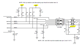
      Not only do I not see the protection diode on your schematic, I also don't see the differential signals pulled up to 3.3V. Please see below shown in the TM4C129 system design guideline. 

    Here is the TI reference design using RJ45 with built-in transformer. As you can see the differential signals are pulled up to 3.3V. 

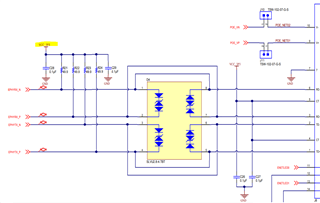
    Here is another view of the LaunchPad schematic with the differential signals pulled up to 3.3V and also the protection diode in place. 

    It is very likely the MCU is damaged and only partially working. 

  • We will redesign the PCB and consider above point.

    But in our new series of instrument client want POE i.e Power the Instrument using Ethernet.

    We have purchased POE Ethernet switch and we have used TPS2379 POE controller in our design.

    We tested the communication but it is not working.

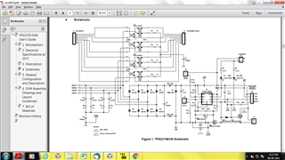
    We have schematic device as per

    TPS2379 EVM User’s Guide please check attached file.

    So Please guide us If POE is possible in this controller

    Thanks and Regards,

    Anushka

  • Hi Anushka,

      Sorry, if this is a question concerning TPS2379 then I cannot support it as I don't have any experience with it. Please open a new thread specifying TPS2379 as the part number for the thread. This will route your post to the Power Management forum where the experts there can better assist your questions. I can only assist in questions related to MCU side. As you can see on the TI reference design I showed earlier, it is a POE design. So from the MCU point of view, there is no issue to supply power via POE. Again, for questions concerning TPS2379, please open a new thread stating it as the part number for support. 

  • Thank you Charles Tsai for your valuable reply