This thread has been locked.

If you have a related question, please click the "Ask a related question" button in the top right corner. The newly created question will be automatically linked to this question.

TM4C1294NCPDT: Explanation for jitter in PLL output

Part Number: TM4C1294NCPDT
Other Parts Discussed in Thread: TM4C1290NCPDT

I don't have a question, but wanted to provide an possible explanation to an issue raised in the related question (the thread for which is now locked).  Perhaps someone from TI can confirm or deny this and provide some detail beyond what is in the data sheet.

Brad Rodriguez (the OP) wrote, "At the moment I am using a TM4C timer to generate a regular 50 usec pulse, triggering on the leading edge, and observing the trailing edge with a digital 'scope. I see about 8 ns of jitter on the trailing edge, of which 2.5 ns can be attributed to the 'scope."

Randy Ott wrote, "I wouldn't be too quick about blaming the PLL for the observed jitter. 8 nS is very close to the 8.333 nS period of the 120 MHz clock...  The PLL really should not jitter that much."

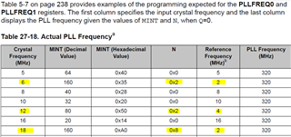
TLDR - I think that the root cause of the jitter is the use of a crystal frequency (25MHz) which is not an exact divisor of 320MHz or 480MHz.  I suspect that the jitter would be greatly reduced if any crystal frequency which was an integer divisor were used instead, such as 5MHz, 10MHz, or 16MHz. 

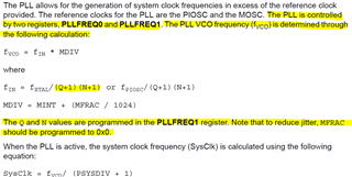
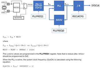
Why does the crystal frequency matter?  It comes down to how a PLL works, and in this case a fractional-N PLL.  A PLL manipulates the voltage which controls the frequency generated by a VCO.  It does that by comparing the phase of two signals (one from a reference and one feedback) and making adjustments to keep them phase locked (thus the name "phase locked loop") and thus equal in frequency.  To get a higher frequency out of the VCO than the reference (from the crystal, in this case), a frequency divider is inserted into the feedback loop between the VCO output and the phase comparator.  If the divider is set to reduce the frequency by 10, for example, the VCO frequency has to be 10X the reference for the divided down version which reaches the phase comparator to equal the reference frequency.  So the frequency divider (in the feedback loop) effectively causes the VCO output frequency to be set to a multiple of the reference, in this case 10X.  That is all pretty straightforward (in concept), and as Randy wrote, should not result in much jitter on the VCO output.

It gets more complicated when you want an output frequency that is some non-integer multiple of the reference.  One option is to divide (prescale) the reference frequency before it reaches the phase comparator, then multiply by a larger factor to get the output.  I haven't been able to figure out whether the TM4C129 is able to do that or not.  If it could, the 25MHz reference could be divided by 5, then multiplied by an integer to reach 320MHz or 480MHz, the frequencies that the VCO supports (which is then divided down to get the 120MHz or whatever system clock).  I think that would also give a low-jitter output.

In this case, however, it seems likely to me that a different technique is being used, with a fractional (actually mixed number) divisor in feedback loop, something that is supported by "fractional-N" PLLs.  Looking at the source code for _SysCtlFrequencyGet, it looks like there is a /32 (five bit) fraction available (and maybe a /1024).  Making up an example with nicer numbers than the real ones, let's say that we had a 16.384MHz crystal (defined as SYSCTL_XTAL_16_3MHZ in sysctl.h) and wanted the VCO to output 320MHz.  That means we need a divider ratio of 19.53125 in the feedback loop of the PLL.  That happens to be 19 17/32, so it works out perfectly for a /32 fractional-N PLL.  Each time a pulse enters the divider, the output either changes or it doesn't; there is no fraction available there.  So it divides by 19 some of the time, and 20 the rest of the time (17/32 of the time) so the average divider ratio comes out right.  It should now be obvious why there is jitter in the output when using a fractional (rather than whole number) ratio; the divider ratio and therefore the output frequency keeps changing between the available frequency steps (multiples of the reference frequency) to get the desired average frequency.

This variation caused by the changing divider ratio can be smoothed out somewhat by filtering the analog voltage output by the phase comparator before it reaches the VCO so the VCO output doesn't track the changes quite as closely.  Search for "PLL loop filter" for more about that (it gets really complicated).  In this case, the PLL loop filter is internal to the MCU and can't be changed.  But it does affect how closely the output tracks the irregular divider output and therefore makes observations such as the jitter (in the OP's example) of 8nS being close to the 8.333 nS period of the 120 MHz clock less directly related to the divider's operation.  I'm not sure if those specific numbers are just coincidence or not, but I am sure that using a fractional divider introduces jitter in the time domain, and corresponding "interesting" (undesirable) effects in the frequency domain.

Whether what I wrote applies in this case is mostly speculation, but it seems to fit the OP's observations and what I have been able to decipher from the source code and datasheet.  It would be nice if the TM4C129 datasheet included a block diagram showing the PLL internals with the prescaler (if it has one) and feedback loop dividers shown so we could better explore the tradeoffs and understand the suggested register values.

Steve

P.S.  I just stumbled across the Wikipedia page for "dual-modulus prescaler".  It appears to work very much like what I described, but is applied to the reference frequency before it reaches the phase comparator.  I am not otherwise familiar with such prescalers, but it seems inevitable that they would introduce jitter in a similar way.  For all I know, the TM4C129 might have one of these instead of or as well as a fractional-N divider in the feedback loop.

  • Hi Steve,

      Thanks for giving your insights. PLL jitters is usually very small, perhaps in the range of < 1ns. 8ns jitter is unheard of. Can you please show the link to the posts by Brad Rodriguez and others. I'd like to read the context of the discussion. I think there is some misunderstanding.   

  • Ok, I found the original post by Brad Rodriguez. 

  • The original post is https://e2e.ti.com/support/microcontrollers/arm-based-microcontrollers-group/arm-based-microcontrollers/f/arm-based-microcontrollers-forum/419897/tm4c129-with-120-mhz-external-clock?keyMatch=TM4C129+LAUNCHPAD

    I created this one by selecting "Ask a related question" from that one, which is supposed to automatically link it to that original question, but I don't find a link in either direction.

  • PLL jitters is usually very small, perhaps in the range of < 1ns. 8ns jitter is unheard of.

    The referenced thread does end with saying

    An update: I am now testing with a high resolution timer, and I am seeing jitter under 1 nsec -- with or without the PLL.  So I think the 8 nsec I was seeing earlier was from my 'scope, not from the MCU.

    I don't have suitable equipment to perform a jitter measurement myself.

  • I saw that too, but I wasn't sure what he had used before switching to a "high resolution timer", so I didn't know what to make of it.  I was also uncertain if he had changed to feeding it with a 120 MHz external oscillator as had been discussed.  If he was still using the same 25MHz crystal reference for the PLL and the same PLL divider settings, it would show that the PLL wasn't the source of the original jitter.  That would fit with his suggestion that "the 8 nsec I was seeing earlier was from my 'scope, not from the MCU" but it still doesn't explain why he made a point of saying that he was "now testing with a high resolution timer" which could be an explanation which had nothing to do with the scope.

    Looking back at what he wrote, I now notice that he suggested that the PLL has an input prescaler and that it is controlled by the Q divider.  That is the kind of info I haven't found in the datasheet (TI - can you confirm it and maybe provide some more info about the PLL?).  With a prescaler like that, I think you could divide 25MHz by 5, then use the N divider to multiply it up to 320MHz or 480MHz without any fractional divisors, avoiding the jitter I was writing about.  Or perhaps the PLL loop filter is good enough to take out the jitter caused by the fractional divisors (I'm guessing not, the datasheet says, "Note that to reduce jitter, MFRAC should be programmed to 0x0."  

    TI - can you tell us what the function of each divider is and what range of values it is acceptable to set them to?  A table like 26-18 in the TM4C1290NCPDT datasheet is nice, but it seems likely that there are other useful combinations of register settings we might like to explore, and it would help in understanding the ones listed there.  For example, sysctl.h defines SYSCTL_XTAL_16_3MHZ and in the comment suggests that it is for a 16.384 MHz crystal.  Is it acceptable to use it even though it isn't listed in Table 26-18?  What about other values which aren't listed in the datasheet table or the source code?

  • I was also uncertain if he had changed to feeding it with a 120 MHz external oscillator as had been discussed. 

    PLL input frequency is limited to 5-25Mhz per datasheet. Feeding a 120Mhz OSC to PLL is wrong. I suppose it is a typo from the OP. 

    Looking back at what he wrote, I now notice that he suggested that the PLL has an input prescaler and that it is controlled by the Q divider.  That is the kind of info I haven't found in the datasheet (TI - can you confirm it and maybe provide some more info about the PLL?).

    Q and N are documented in the datasheet. 

    TI - can you tell us what the function of each divider is and what range of values it is acceptable to set them to?  A table like 26-18 in the TM4C1290NCPDT datasheet is nice, but it seems likely that there are other useful combinations of register settings we might like to explore, and it would help in understanding the ones listed there.  For example, sysctl.h defines SYSCTL_XTAL_16_3MHZ and in the comment suggests that it is for a 16.384 MHz crystal.  Is it acceptable to use it even though it isn't listed in Table 26-18?  What about other values which aren't listed in the datasheet table or the source code?

    Below is a high level diagram I draw to show the various components. Crystal value can be any frequency between 5Mhz to 25Mhz per datasheet.

  • Thanks, Charles, for the diagram.  That is exactly the kind of info I was looking for. 

    I am still having a hard time getting everything to make sense.  In that diagram the prescaler would seem to adjust the crystal frequency by a factor of (N+1)/(Q+1).  That would mean that the equation from the data sheet which is written as fIN = fXTAL / (Q+1) (N+1) should be interpreted (parenthesis added) as fIN = ( fXTAL / (Q+1) ) (N+1).  But looking at the source code for SysCtlVCOGet(), I see this line:

    ui32TempVCO /= ((ui32NDiv + 1) * (ui32QDiv + 1));

    That makes me think the correct order of operations is fIN = fXTAL / ( (Q+1) (N+1) ) and that the prescaler block in the diagram should say

        1

    ----------

    (Q+1)(N+1)

    Of course it doesn't matter which is correct if you set Q to zero (more on that below).

    Looking at SysCtlClockFreqSet(), in the case where ui32Config contains SYSCTL_USE_PLL, the "system divider" is set to the VCO frequency (either 320MHz or 480MHz) divided by the requested system clock frequency, with the divisor always rounded up to avoid the result from exceeding the requested frequency.  That eventually affects what gets written to SYSCTL_RSCLKCFG which makes sense with the "/ R" block in the diagram.  With "R" defined this way, it is equal to (PSYSDIV + 1).  So that block could be labeled 1/(PSYSDIV + 1).

    So to summarize (if I have it right):

    • The crystal frequency should be 5MHz to 25MHz.  It must be 25MHz if you want to use Ethernet.
    • The prescaler can be used to divide that frequency down to anything in the range of 4MHz to 30MHz for the PLL's reference frequency, fIN.
    • The PLL will multiply fIN by M, which is a mixed number with an integer part and a /1024 part, MINT+MFRAC/1024, to get the VCO frequency which should be 320MHz or 480MHz.  You get less jitter if MFRAC is 0, which will be the case if the VCO frequency is an exact multiple of fIN.  Function _SysCtlFrequencyGet() calls this P instead of M.
    • The VCO frequency will be divided by (PSYSDIV + 1) to get the system clock, which may be as high as 120MHz and at least as low as 6MHz (that is the lowest value shown in Table 26-17 in the TM4C1290NPDT data sheet).  To get the maximum CPU performance (120MHz clock), you need to use 480MHz as there is no way to divide 320MHz by an integer and get 120MHz.

    There are a few things I still don't have worked out, but they shouldn't matter in most situations:

    • I don't understand what the Q divider is good for if 25MHz is really the max crystal frequency.  Footnote "a" below Table 5-7 says, "For all examples listed, Q=0", so maybe there aren't any good examples.  If I understand the prescaler correctly, you can achieve all of the useful divider ratios by changing N. The biggest it would need to be is 5, as the next higher value (6) leads to a reference frequency below 4MHz, the lowest that is supported (25MHz / (6+1) = 3.57MHz).  Unless, perhaps, Zhaohong Zhang was right in the related thread where he wrote, "According to the datasheet, I think that PLL can take 120 MHz as input".  If that is true, perhaps you could use a larger divide ratio than N by itself could provide.
    • The footnote for Table 5-6 says, "The use of non-integer divisors introduce additional jitter which may affect interface performance."  The context of that is the PSYSDIV divider, which I believe only supports integer values.  Perhaps there is confusion with the M divider, for which that makes sense.
    • The paragraph after that says, " Table 5-7 on page 231 shows the actual PLL frequency and error for a given crystal choice."  But all of the examples in table 5-7 result in zero error in the actual PLL frequency.  That isn't very helpful in figuring out how it works.  Some less perfect examples would be nice.
    • It also says there, "The internal translation provides a translation within ±1% of the targeted PLL VCO frequency."  Does that imply that the VCO can deviate at least ± 1% from its nominal frequencies (320MHz or 480MHz)?  If so, you should be able to use any crystal frequency within the range of 5MHz to 25MHz and get the PLL to lock as it can choose a value for M to get within 1%.  But the way SysCtlClockSet() is written (using a table lookup), you have to use one of the pre-defined crystal frequencies (or set the registers yourself). In other words, I think you could use any crystal frequency within the 5MHz to 25MHz range if you set the registers yourself rather than using SysCtlClockSet().
      • I think it should be be able to get much closer than 1%, as the minimum value for M SysCtlClockSet() is about 11 and the fraction part is x/1024.  So 1 part in 1024 out of 11 is about 1 part in 11000, less than 0.01%.
    • The VCO must be able to handle variations much larger than ±1%, since you can use it with the PIOSC as the reference, and the PIOSC has a tolerance of ±10% at temperatures below 0C.  If you use a crystal with a tighter tolerance than that, you could probably program the M divider to aim for a frequency anywhere within about 10% of 320MHz or 480MHz and be fine. 
      • This suggests that it might be possible to overclock the MCU up to 10%; consider that you might do so inadvertently by setting it up for the spec'd max frequency using the PIOSC.  If the PIOSC frequency then happens to be at the the top end of its ±10% tolerance range (below 0C), the VCO would run 10% fast.  On the other hand, perhaps it can handle running 10% fast only when the temperature is low.  You would want to use an accurate frequency reference if you set the PLL to aim for an overclocked frequency, as you wouldn't want the combination of the intentional overclocking and error in your frequency reference to push the actual frequency more than 10% over, unless  you get a spec for the VCO frequency range from TI which indicates that is OK.  If you tried it and the PLL wouldn't lock, that could cause trouble.
      • With certain crystal frequencies, you might want to aim for something slightly different than 320MHz or 480MHz to minimize jitter by setting MFRAC to 0 rather than to the fraction that lets you hit 320MHz or 480MHz as closely as possible.  For example, if you use a 16.384MHz crystal, SysCtlClockSet() will set M to a mixed number (MFRAC not 0).  I'm suggesting that might not be necessary; setting M to an integer and letting the VCO run a bit further from its nominal frequency would lower the jitter.  You would want to use an accurate frequency reference, such that the tolerance stacking of the intentional difference from nominal and the tolerance of the reference combined stay within 10%.
      • Another reason you might want to set the VCO frequency to be slightly different than 320MHz or 480MHz is that doing so may let you hit specific PWM frequencies more exactly.  For example, if you use a 16.384MHz crystal, SysCtlClockSet() will try to set M to a fractional value in order to get as close as possible to the nominal VCO target frequency (it is possible to hit 320MHz exactly with M set to 19 544/1024, as the first message in this thread describes).  Unfortunately, neither 320MHz or 480MHz divide down exactly (by an integer) to 32.768KHz, as you might want for a timing application (although you can get very close).  In this example, if you use any integer value for M, the resulting VCO frequency can be divided by an integer to hit 32.768KHz exactly (because 16.384MHz is an exact multiple of 32.768KHz).  In general it might not be necessary for M to be an integer to achieve a specific PWM frequency exactly, but as described in the previous point, doing so will also lower the jitter so you might as well choose crystal and VCO frequencies that let you achieve both benefits.
    • Table 5-6 and Table 26-17 are identical, as is some of the surrounding material.  That is redundant, but a lot better than being contradictory Slight smile
    • I don't understand why these lines from function SysCtlClockFreqSet() are needed.  Apparently they adjust for _SysCtlFrequencyGet() returning twice the system clock frequency.  Is there a distinction between the SysCtlFrequency and the SysCtlClockFreq?  Are they both distinct from SysCtlVCO?  I could probably figure that out but it is after 5:00 on Friday...

    Steve

  • That makes me think the correct order of operations is fIN = fXTAL / ( (Q+1) (N+1) ) and that the prescaler block in the diagram should say

        1

    ----------

    (Q+1)(N+1)

    Of course it doesn't matter which is correct if you set Q to zero (more on that below).

    Hi Steve,

      You are absolutely correct. Sorry for the confusion. In order for the below reference frequency to hold, the N must be in the denominator as in your equation. You have too many questions for me to digest and it's Friday. I will go through your questions and reply on Monday.