This thread has been locked.

If you have a related question, please click the "Ask a related question" button in the top right corner. The newly created question will be automatically linked to this question.

TMS570LC4357: TMS570LC4357

Part Number: TMS570LC4357
Other Parts Discussed in Thread: SEGGER

Hi TI Community,

I am currently working on debugging the TMS570LC437 MCU with a segger JLink Plus Debugger and a custom interface board to connect the 20 pin JTAG connector with the pinouts of the MCU.

The nTRST, TMS, TDI, TDO, TCK, RTCK ports from the Debugger JTAG connector are connected to the corresponding JTAG pins of the MCU. I have not connected the DBGRQ and RESET pins for now.

I am constantly getting this error message in my ozone software once I connect everything and when I looked it up, it is claimed to be caused by some connection error.

TotalIRLen = ?, IRPrint = 0x..000000000000000000000000
Can not find ICE-Pick (IRLen mismatch). Expected 0x00000006, found: 0x00000280
J-Link script: ICEPick found, enabling Cortex-R5 core.
TotalIRLen = ?, IRPrint = 0x..000000000000000000000000
Can not find ICE-Pick (IDCODE mismatch). Expected 0x0000002F, found: 0xA0002108
TotalIRLen = ?, IRPrint = 0x..000000000000000000000000
Can not find DAP (IDCODE mismatch)
InitTarget() end
InitTarget() start
Executing InitTarget()

the interface board connects these standard JTAG pinouts to the MCU. I have not yet attached any pull-up or pull-down resistors to any of the pins and am supplying 3.3V to the VTref port.

Is there pull-up and pull-down resistors needed for communicating with this MCU and if yes which pins need which ones and if a pull-up resistor is needed, should it be pulled up to 3.3V or 5V??

Looking forward to any help,

Thank you,

Regards,

Aadi

  • Hi Aadi,

    I don't know the circuitry for nTRST in JLNK debugger. If it is open-drain, an external pull-up is needed. Otherwise we recommend to add an pull-down to nTRST.

  • ok thanks so I will add a pull down resistor of around 10K ohms between nTRST and GND. are there any other such Resistors needed. I had to add one pull-down between TDO and GND as well since, it was giving me "Constant TDO HIGH" error and "failed to connect" initially which went away as soon as I added a pull-down resistor. Currently I get no issues by it just says Could not Connect to Target. I sense, the JTAG pins of the Microcontroller might be by default locked and I do not know how to unlock it... 

  • e.pdf

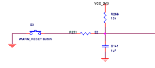
    The Schematics of the Development Board I am using. Where Can I find the Reset Button to Reset nTRST to GND and start debugging the MCU??

  • This is nRST button S3 on HDK:

  • nTRST is JTAG “Test Reset”. It is low active. The nTRST is used for an asynchronous reset of the state machine of the JTAG Test Access Port (TAP). The debugger drives it by a push-pull driver. It resets the TAP by a certain JTAG sequence. The target device requires that the nTRST is first held low for a few TCK cycles and then raised after the TCK signal has started running, so the device can detect a rising edge on nTRST.

    A pull-down resistor should be added onto nTRST on target side. It ensures the on-chip debug logic is inactive when the debugger is not connected.

    For TDO/TMS/TCK etc, you can use the internal the pull up or down instead. If the JTAG signal trace is long, please add a series termination resistor to TCK trace.