This thread has been locked.

If you have a related question, please click the "Ask a related question" button in the top right corner. The newly created question will be automatically linked to this question.

TMS570LC4357: SCI Transmit (and maybe Receive) using DMA

Part Number: TMS570LC4357
Other Parts Discussed in Thread: HALCOGEN

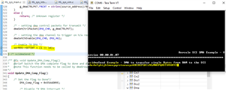
I'd like to set up my SCI to use DMA on transmit, to print stuff without tying up the CPU.  At 230400 baud, a character output takes 42 usec, so printing 25 characters takes 1 msec if the CPU polls, as with sciSend().

There was the following discussion about DMA on receive, but I can't tell what was the outcome...

https://e2e.ti.com/support/microcontrollers/arm-based-microcontrollers-group/arm-based-microcontrollers/f/arm-based-microcontrollers-forum/817131/tms570lc4357-sci-receive-using-dma

Thanks for all help.

  • Hi,

    Transmit DMA request is enabled by the setting SET TX DMA and SET TX INT bits. If the SET TX DMA bit is set, then a TX DMA request is sent to the DMA when data is written to SCITD and TXRDY is set. 

    /*Enable SCI3 Transmit and SCI1 Receive DMA Request*/
    sciREG3->SETINT |= SCI_SET_TX_DMA | SCI_TX_INT;

  • The receiver DMA request is set when a frame is received successfully and DMA functionality has been previously enabled. The RXRDY flag is set when the SCI transfers newly received data from the SCIRXSHF register to the SCIRD buffer. The RXRDY flag therefore indicates that the SCI has new data to be read. Receive DMA requests are enabled by the SET RX INT bit.

    /*Enable SCI3 Receive DMA Request*/

    sciREG3->SETINT |= SCI_SET_RX_DMA | SCI_SET_RX_DMA_ALL | SCI_RX_INT;

  • I don't see SCI_SET_TX_DMA defined, but the chip specs says bit 16, so I have the following code:

    sciInit();
    /*Enable SCI3 Transmit and SCI3 Transmit DMA Request*/
    #define SCI_SET_TX_DMA (1 << 16)
    printf("SCI_TX_INT=0x%x\n", SCI_TX_INT);
    sciREG3->SETINT |= SCI_SET_TX_DMA | SCI_TX_INT;
    printf("sciREG3->SETINT=0x%x\n", sciREG3->SETINT);

    The output shows SETINT having 0x0 rather than having 0x10100  at least, which seems to indicate something is off.

    SCI_TX_INT=0x100
    sciREG3->SETINT=0x0
    This is a long string which is used purely to eat up time
    udiff=2462.670

    The display via sciSend remains at 2.4 msec, (at 230400 baud), the same as for polled output.

    I assume REG3 is the console channel used for sciSend().

    Is there some test project that demonstrates this?

    Thanks.

  • Hi Peter,

    The output shows SETINT having 0x0 rather than having 0x10100  at least, which seems to indicate something is off.

    Before configuring the SCI registers, you have to set the RESET bit of SCIGCR0 register to 1, and clear the SWnRST bit of SCIGCR1 register to 0

    The display via sciSend remains at 2.4 msec, (at 230400 baud), the same as for polled output.

    The transmission time for 1 char is: (8 bits + 2 stop bits)/230400 = 0.0434 ms. Transmitting a char in interrupt mode doesn't save you time than using poll mode.

  • I added the following GCRx writes, and the serial port is no longer outputting anything.  There must be other stuff I need to do.

    sciInit();
    /*Enable SCI3 Transmit and SCI3 Transmit DMA Request*/
    #define RESET (1 << 0)
    #define SWnRST (1 << 7)
    sciREG1->GCR0 |= RESET;
    sciREG1->GCR1 &= ~SWnRST;
    #define SCI_SET_TX_DMA (1 << 16)
    printf("SCI_TX_INT=0x%x\n", SCI_TX_INT);
    sciREG3->SETINT |= SCI_SET_TX_DMA | SCI_TX_INT;
    uint32 setint = sciREG3->SETINT;
    printf("sciREG3->SETINT=0x%x\n", setint);

    I didn't show the code doing the print timing (using polled or DMA), but it is...

    timer_delay(1); // let previous output fully drain

    uint64 c_start = timer_cread();
    printf("This is a long string which is used purely to eat up time\n");
    uint64 c_end = timer_cread();
    float udiff = timer_udiff(c_start, c_end);
    timer_delay(1); // let output fully drain
    printf("udiff=%1.3f\n", udiff);

    which produced...


    This is a long string which is used purely to eat up time
    udiff=2462.390

    Using DMA makes a world of difference, as instead of the CPU tied up for 2.4 msec, it goes on its merry way doing other (important) stuff.  With DMA, the udiff should be showing much less than a few usec.

    Using DMA (or interrupt IO) is the general way systems (OSs) service low-speed devices without wasting CPU time.  The implementation of sciSend() is actually pretty limited, since it requires the "user" to babysit the hardware on every line of output (essentially every call to sciSend()).  I will be implementing a write() layer [ similar to Unix/Linux system call] that copies the user-sent data into a system buffer (say 1KB), from which DMA will suck out data (using repeated sciSend()).  Hence, the user "application" will not block, until the 1KB buffer is exceeded.  Alternatively, (in a different mode) user output could be tail-dropped (and app not block) if the late print information is not important for display.

    Of course, I need to get the DMA mode running first.

    Thanks for all help.

  • Hello,

    The printf function is a standard C function used to output text. It outputs text to CCS console rather than a UART COM port. The printf doesn't use any SCI functions (sciSent() or sciReceive()). 

    Using DMA can relieve the CPU from the burden of copying large blocks of data, so the CPU can perform other operation while the DMA is transferring data between memory and SCI registers. As mentioned in my previous post,  the DMA request is generated when data is written to SCITD and TXRDY is set (for SCI TX), and generated when SCI transfers newly received data from the SCIRXSHF register to the SCIRD buffer. The time taken by SCI is mainly dependent on the SCI baudrate.

    Here is an example of using DMA + SCI:

    https://www.ti.com/lit/an/spna213/spna213.pdf?ts=1653508311576&ref_url=https%253A%252F%252Fwww.google.com%252F

    The SCI/LIN module on TMS570LC4357 supports a multi-buffered receiver and transmitter. SCI/LIN module has eight separate Receive and transmit buffers. Multi buffered mode is enabled by setting the MBUF MODE bit. The example above supports multi-buffered mode too.

  • Hi,

    I'm using a popular embedded version of printf(), not whatever CCS offers.  I currently have the low end hooked up ultimately to sciSend(sciREG1,...), but could just as easily use another sciREG for output.  Halcogen shows the console using SCI1 on the XL2-570LC43.

    I was able to build the mentioned example package for the XL2-570LC43, but (of course) was not able to run it, since the package sources is for another board.

    I copied the appropriate code pieces from sys_main.c to HL_sys_main.c (for the XL2-570LC43), and got the following errors:

    source/subdir_rules.mk:9: recipe for target 'source/HL_sys_main.obj' failed
    "../source/HL_sys_main.c", line 183: error #20: identifier "scilinREG" is undefined
    "../source/HL_sys_main.c", line 434: warning #112-D: statement is unreachable
    "../source/HL_sys_main.c", line 450: warning #179-D: variable "cSCI_printfbuffer" was declared but never referenced
    "../source/HL_sys_main.c", line 451: warning #179-D: variable "length" was declared but never referenced
    "../source/HL_sys_main.c", line 483: error #20: identifier "scilinREG" is undefined
    "../source/HL_sys_main.c", line 486: error #167: too few arguments in function call
    "../source/HL_sys_main.c", line 491: warning #190-D: enumerated type mixed with another type
    "../source/HL_sys_main.c", line 527: error #20: identifier "dmaBTCAInterrupt" is undefined
    "../source/HL_sys_main.c", line 560: error #20: identifier "scilinREG" is undefined
    "../source/HL_sys_main.c", line 567: error #20: identifier "linREG" is undefined
    "../source/HL_sys_main.c", line 597: error #20: identifier "scilinREG" is undefined
    "../source/HL_sys_main.c", line 610: error #20: identifier "scilinREG" is undefined
    "../source/HL_sys_main.c", line 627: error #20: identifier "scilinREG" is undefined
    9 errors detected in the compilation of "../source/HL_sys_main.c".

    So, I substitute scilinREG with sciREG1.

    The code has a comment saying sciREG1 is not supported (by DMA hardware or the software???).

    Now the two errors are dmaEnableInterrupt() requiring a dmaIntGroup_t argument (line 167), and undefined dmaBTCAInterrupt (line 527).

    How do I work around these?

    Thank you very much for the help.

  • I just copied over dmaBTCAInterrupt() from sys_dma.c and use DMA_INTA for dmaEnableInterrupt().  Comments say BTC (block transfer complete) interrupt is routed to group A, but I'm just doing this "blindly."  Now need to go into Halcogen and see what DMA-related hardware needs to be enabled/set-up.

  • I've modified the code as much as I could, but the first call to scidmaSend() doesn't seem to have done anything, as the DMA interrupt ISR does not happen.  I'm sending to the console port, sciREG1, and the initial non-DMA output happens fine.  I walked through the scidmaSend() code, and the registers being configured seems reasonable. I somewhat blindly called dmaReqAssign() so DMA_CH0 is hooked to pin 31 (sciREG1???); don't know if this is right.

    Is it possible for me to upload my HL_sys_main.c, so you could take a look, and maybe walk through the code with a debugger?  Thank you very much.

    /* assigning dma request: channel-0 with request line - 1 - TX*/
    /* DMA Request 29 is for LIN ( SCI2) Transmit */
    /* Refer Data sheet - Default DMA Request Map section */
    // dmaReqAssign(DMA_CH0,29);
    dmaReqAssign(DMA_CH0, 31); // sciREG1 (see below)

  • The code has a comment saying sciREG1 is not supported (by DMA hardware or the software???).

    The example doesn't support sciREG1. All the SCI modules support DMA.

  • Now the two errors are dmaEnableInterrupt() requiring a dmaIntGroup_t argument (line 167), and undefined dmaBTCAInterrupt (line 527).

    How do I work around these?

    dmaEnableInterrupt(uint32 channel, dmaInterrupt_t inttype)  --> used for tms570lsx devices

    dmaEnableInterrupt(dmaChannel_t channel, dmaInterrupt_t inttype, dmaIntGroup_t group)  --> used by TMS570LC43x and RM57 device. 

    Example:

    dmaEnableInterrupt(DMA_CH0, BTC, DMA_INTA); 

  • so DMA_CH0 is hooked to pin 31 (sciREG1???); don't know if this is right.

    No, it is not correct

    The following DMA request lines are assigned to SCIs:

    SCI1_TX       DMA_REQ29
    SCI1_RX      DMA_REQ28

    SCI2_TX      DMA_REQ40
    SCI2_RX      DMA_REQ41

    SCI3_TX        DMA_REQ31
    SCI3_RX        DMA_REQ30

    SCI4_TX       DMA_REQ43
    SCI4_RX       DMA_REQ42

    If you use SCI1 (or LIN1/SCI1), the DMA request line is 29 for TX and 28 for RX:

    dmaReqAssign(DMA_CH0, 29);  //SCI1 RX

    dmaReqAssign(DMA_CH1, 28);  //SCI1 TX

  • The relevant code section is as below.  I have since done some minor edits for using sciREG1.  In any case, the "NOTUSED" section was the original code, which claims 31 is for sciREG1.  I tried looking at the Technical Reference Manual while single-stepping the code and the Manual seems to say 31 was a proper value.  The mapping bits are confusing, but seem to say some clumps of bits at the right place (bits 24 to 29) maps to a particular DMA channel (0).

    I just tried the 29 value (presumably sciREG1 TX) and the scidmaSend() is still hanging as before.

    Note that while using the 31 value, I'm seeing a breakpoint on the dmaBTCAInterrupt firing off _before_ reaching scidmaSend(), so 31 is routing something to that interrupt.  Unfortunately, that interrupt does not happen once scidmaSend() is called.


    /* Enable Interrupt after reception of data */
    dmaEnableInterrupt(DMA_CH0, BTC, DMA_INTA); /* DMA_CH0 is highest priority */

    /* assigning dma request: channel-0 with request line - 1 - TX*/
    /* DMA Request 29 is for LIN ( SCI2) Transmit */
    /* Refer Data sheet - Default DMA Request Map section */
    // dmaReqAssign(DMA_CH0,29);
    dmaReqAssign(DMA_CH0, 31); // sciREG1 (see below)
    }
    #ifdef NOTUSED
    else if (sci == sciREG1) {
    return; /* SCI1 is not supported at this time */

    /* Enable Interrupt after reception of data */
    /* dmaEnableInterrupt(DMA_CH1, BTC); // DMA_CH0 is highest priority */

    /* assigning dma request: channel-0 with request line - 1 - TX*/
    /* DMA Request 31 is for SCI1 Transmit */
    /* Refer Data sheet - Default DMA Request Map section */
    /*dmaReqAssign(DMA_CH1,31); */
    }
    #endif // NOTUSED
    else {
    return; /* Unknown register */
    }

  • The BTCA interrupt was due to the sci_printf() call, which uses sciSend(), that happened after the call to _enable_IRQ().  It happened whether I used 31 or 29.  The original code was meant to use sciREG1 to display test status while testing linREG1 (scilinREG), so it was fine.  I moved the sci_printf() before scidmaInit(), to alleviate the problem.  I was under the impression that sciSend() could be used even after scidmaInit() and _enable_IRQ() have been called, but that's probably not right.

    I was hoping 29 or 31 would now work, but that's not the case and the behavior after scidmaSend() remains the same.  It's as if scidmaSend() has some issue with actually kicking off the DMA, as the display string doesn't show up (unlike in the prior situation with sci_printf()/sciSend() sending its string out (and causing the BTCA interrupt)).  I step through the scidmaSend() code and it looks fine; I really can't see anything I can change in it to fix the problem.

    Thanks.

    sci_printf("scidmaSend Example - DMA to transfer single Bytes from RAM to the SCI\n\r");

    /* Init serREG for DMA transfers */
    scidmaInit(serREG); /* Requires sciInit to be called first */

    /* Enable CPU Interrupts */
    _enable_IRQ();

    // sci_printf("scidmaSend Example - DMA to transfer single Bytes from RAM to the SCI\n\r");

    scidmaSend(buffer);

    /* Enter Code Here but do not call scidmaSend again */

    /* Wait for the DMA interrupt ISR to set the Flag */
    while(DMA_Comp_Flag != 0x55AAD09E){
    IDLECOUNT++;
    }

    /* scidmaSend is complete and can be called again */

    sci_printf("\n\r\n\r");

  • I would have expected these last lines in scidmaSend() to have kicked off the DMA and displayed the test string (with serREG == sciREG1).  But, I see nothing on the terminal.

    /* - setting dma control packets for transmit */
    dmaSetCtrlPacket(DMA_CH0, g_dmaCTRLPKT);

    /* - setting the dma channel to trigger on h/w request */
    dmaSetChEnable(DMA_CH0, DMA_HW);

    /* Enable TX DMA */
    serREG->SETINT = (1 << 16);

    } /* scidmaSend */

  • So, out of frustration, I replaced scidmaSend() with sciSend() and the test string shows up fine, with the BTCA interrupt triggering. With the BTCAOFFSET being 0, the dmaGroupANotification() is not called (as somewhat expected).  So, it's a matter of getting scidmaSend() to do the right thing...

    /* Init serREG for DMA transfers */

    TMS570LC4357: SCI Receive using DMA


    scidmaInit(serREG); /* Requires sciInit to be called first */

    /* Enable CPU Interrupts */
    _enable_IRQ();

    // sci_printf("scidmaSend Example - DMA to transfer single Bytes from RAM to the SCI\n\r");

    // scidmaSend(buffer);
    sciSend(sciREG1, strlen(buffer), buffer);

    /* Enter Code Here but do not call scidmaSend again */

    /* Wait for the DMA interrupt ISR to set the Flag */
    while(DMA_Comp_Flag != 0x55AAD09E){
    IDLECOUNT++;
    }

  • In the scidmaSend() code, there is mention that the address needs to be adjusted for big endian (and the code presumably handles only little-endian now).  In stepping through the code, I'm running big endian.  Would this be a problem?  Or does it only affect the output of the test string, not displaying it properly?  I'd expect the DMA would still transfer as many bytes of data as configured.  So confusing...

    void scidmaSend(char *source_address)
    {
    #if ((__little_endian__ == 1) || (__LITTLE_ENDIAN__ == 1))
    uint8 dest_addr_offset = 0; /* 0 for LE */
    #else
    uint8 dest_addr_offset = 3; /* 3 for BE */
    #endif

    /* Wait for the DMA to complete any existing transfers */
    while(DMA_Comp_Flag != 0x55AAD09E);

    /* Reset the Flag to not Done*/
    DMA_Comp_Flag = ~0x55AAD09E;

    /* - Populate dma control packets structure */
    g_dmaCTRLPKT.SADD = (uint32) source_address;

    if (((serREG->GCR1 >> 10U) & 1U) == 0U) { /* check if not multibuffer mode, note sciREG1 is not multibuffer */
    g_dmaCTRLPKT.DADD = (uint32)(&(serREG->TD))+dest_addr_offset; /* In big endianism devices, the destination address needs to be adjusted */
    g_dmaCTRLPKT.RDSIZE = ACCESS_8_BIT; /* read size */
    g_dmaCTRLPKT.WRSIZE = ACCESS_8_BIT; /* write size */
    g_dmaCTRLPKT.FRCNT = strlen(source_address); /* frame count */
    }
    else if (serREG == linREG1) {
    g_dmaCTRLPKT.DADD = (uint32)(&(linREG1->TDx));
    /* In big endianism devices, the destination address needs to be adjusted
    * for byte access. The DMA is a big endian master. But the SCI Transmit buffer
    * is accessible at the least significant byte. */
    g_dmaCTRLPKT.RDSIZE = ACCESS_32_BIT; /* read size */
    g_dmaCTRLPKT.WRSIZE = ACCESS_32_BIT; /* write size */
    g_dmaCTRLPKT.FRCNT = strlen(source_address)/4+8; /* frame count */
    }
    else {
    return; /* Unknown register */

    }

  • I'm baffled.  After many hours of trying to get dmasciSend() to send a string on sciREG1, nothing is happening.  I've gone through the configuration(s) dozen of time and everything seems reasonable.  I've tried various values with no success.  In the sample code, I see comments like the address needs to be set differently for big endian systems, but I see no mention of any of this in the Technical Reference Manual (which is skimpy on a lot of specific detailed items, given the massive amounts of registers and options).  The sample code has comments that seem to conflict with documentation in the manual.  Getting an example code to run on a basic device shouldn't be that difficult.

    I have uploaded my HL_sys_main.c, which should insert into a basic TMS XL2-570LC43 project cleanly.  The addition of Update_DMA_Comp_Flag() to notification.c is optional at this point, since the DMA operation doesn't even seem to be happening at all.  If possible, please run this project and help me debug the problem, possibly with TI hardware support.

    https://filedropper.com/d/s/HnrWFXoj2ZeQyNpI8nxjBtKbHKbw3R

    Thank you very, very, much.

  • Hi Peter,

    I am not able to open the like:

  • Hi Peter,

    Please refer to my example:

    SCI3 is to receive data from SCI1:

    /** @file HL_sys_main.c 
    *   @brief Application main file
    *   @date 11-Dec-2018
    *   @version 04.07.01
    *
    *   This file contains an empty main function,
    *   which can be used for the application.
    */
    
    /* 
    * Copyright (C) 2009-2018 Texas Instruments Incorporated - www.ti.com  
    * 
    * 
    *  Redistribution and use in source and binary forms, with or without 
    *  modification, are permitted provided that the following conditions 
    *  are met:
    *
    *    Redistributions of source code must retain the above copyright 
    *    notice, this list of conditions and the following disclaimer.
    *
    *    Redistributions in binary form must reproduce the above copyright
    *    notice, this list of conditions and the following disclaimer in the 
    *    documentation and/or other materials provided with the   
    *    distribution.
    *
    *    Neither the name of Texas Instruments Incorporated nor the names of
    *    its contributors may be used to endorse or promote products derived
    *    from this software without specific prior written permission.
    *
    *  THIS SOFTWARE IS PROVIDED BY THE COPYRIGHT HOLDERS AND CONTRIBUTORS 
    *  "AS IS" AND ANY EXPRESS OR IMPLIED WARRANTIES, INCLUDING, BUT NOT 
    *  LIMITED TO, THE IMPLIED WARRANTIES OF MERCHANTABILITY AND FITNESS FOR
    *  A PARTICULAR PURPOSE ARE DISCLAIMED. IN NO EVENT SHALL THE COPYRIGHT 
    *  OWNER OR CONTRIBUTORS BE LIABLE FOR ANY DIRECT, INDIRECT, INCIDENTAL, 
    *  SPECIAL, EXEMPLARY, OR CONSEQUENTIAL DAMAGES (INCLUDING, BUT NOT 
    *  LIMITED TO, PROCUREMENT OF SUBSTITUTE GOODS OR SERVICES; LOSS OF USE,
    *  DATA, OR PROFITS; OR BUSINESS INTERRUPTION) HOWEVER CAUSED AND ON ANY
    *  THEORY OF LIABILITY, WHETHER IN CONTRACT, STRICT LIABILITY, OR TORT 
    *  (INCLUDING NEGLIGENCE OR OTHERWISE) ARISING IN ANY WAY OUT OF THE USE 
    *  OF THIS SOFTWARE, EVEN IF ADVISED OF THE POSSIBILITY OF SUCH DAMAGE.
    *
    */
    
    
    /* USER CODE BEGIN (0) */
    /* USER CODE END */
    
    /* Include Files */
    
    #include "HL_sys_common.h"
    
    /* USER CODE BEGIN (1) */
    #include "HL_sys_dma.h"
    #include "HL_sci.h"
    //#include "stdio.h"
    /* USER CODE END */
    
    /** @fn void main(void)
    *   @brief Application main function
    *   @note This function is empty by default.
    *
    *   This function is called after startup.
    *   The user can use this function to implement the application.
    */
    
    /* USER CODE BEGIN (2) */
    #define size 128
    /* External connection (SCI3 TX -> SCI4 RX) is needed in case LOOPBACKMODE is defined as 0 */
    #define LOOPBACKMODE 0
    
    /* Tx and Rx data buffer */
    /* edit jc 20160102: put these variables in write trough memory, so that DMA actions are written from cache to memory */
    #pragma SET_DATA_SECTION(".sharedRAM")
    uint8_t TX_DATA[size] = {0};
    uint8_t RX_DATA[size] = {0};
    #pragma SET_DATA_SECTION()
    
    /* Addresses of SCI 8-bit TX/Rx data */
    #if ((__little_endian__ == 1) || (__LITTLE_ENDIAN__ == 1))
    #define SCI3_TX_ADDR ((uint32_t)(&(sciREG3->TD)))
    #define SCI3_RX_ADDR ((uint32_t)(&(sciREG3->RD)))
    
    #define SCI4_TX_ADDR ((uint32_t)(&(sciREG4->TD)))
    #define SCI4_RX_ADDR ((uint32_t)(&(sciREG4->RD)))
    
    #define SCI1_TX_ADDR ((uint32_t)(&(sciREG1->TD)))
    #define SCI1_RX_ADDR ((uint32_t)(&(sciREG1->RD)))
    
    #define SCI2_TX_ADDR ((uint32_t)(&(sciREG2->TD)))
    #define SCI2_RX_ADDR ((uint32_t)(&(sciREG2->RD)))
    
    #else
    #define SCI3_TX_ADDR ((uint32_t)(&(sciREG3->TD)) + 3)
    #define SCI3_RX_ADDR ((uint32_t)(&(sciREG3->RD)) + 3)
    
    #define SCI4_TX_ADDR ((uint32_t)(&(sciREG4->TD)) + 3)
    #define SCI4_RX_ADDR ((uint32_t)(&(sciREG4->RD)) + 3)
    
    #define SCI1_TX_ADDR ((uint32_t)(&(sciREG1->TD)) + 3)
    #define SCI1_RX_ADDR ((uint32_t)(&(sciREG1->RD)) + 3)
    
    #define SCI2_TX_ADDR ((uint32_t)(&(sciREG2->TD)) + 3)
    #define SCI2_RX_ADDR ((uint32_t)(&(sciREG2->RD)) + 3)
    #endif
    
    #define DMA_SCI1_TX  DMA_REQ29
    #define DMA_SCI1_RX  DMA_REQ28
    
    #define DMA_SCI2_TX  DMA_REQ40
    #define DMA_SCI2_RX  DMA_REQ41
    
    #define DMA_SCI3_TX  DMA_REQ31
    #define DMA_SCI3_RX  DMA_REQ30
    
    #define DMA_SCI4_TX  DMA_REQ43
    #define DMA_SCI4_RX  DMA_REQ42
    
    #define SCI_SET_TX_DMA      (1<<16)
    #define SCI_SET_RX_DMA      (1<<17)
    #define SCI_SET_RX_DMA_ALL  (1<<18)
    
    unsigned int Ch0_HBC_Flag;
    unsigned int Ch1_HBC_Flag;
    /* USER CODE END */
    
    int main(void)
    {
    /* USER CODE BEGIN (3) */
    	uint32 sciTxData, sciRxData, errCount=0;
    	int i;
    	g_dmaCTRL g_dmaCTRLPKT1, g_dmaCTRLPKT2;
    
    	/*Load source data*/
    	for (i=0; i<size; i++)
    	{
    		TX_DATA[i] = i;
    	}
    
    	/*Initialize SCI*/
    	sciInit();
    
    	Ch1_HBC_Flag = 0;
    
        /* Enable Block Transfer Complete interrupt for the receive after transfer complete */
        dmaEnableInterrupt(DMA_CH1, BTC, DMA_INTA);
    
    #if LOOPBACKMODE == 1
    	/* Enable SCI loopback */
    	sciEnableLoopback(sciREG1, Digital_Lbk);
    	while (((sciREG1->FLR & SCI_TX_INT) == 0U) || ((sciREG3->FLR & 0x4) == 0x4))
        {
    	} /* Wait */
    
    	/*Assign DMA request SCI3 transmit to Channel 0*/
    	dmaReqAssign(DMA_CH0, DMA_SCI3_TX);
    
    	/*Assign DMA request SCI3 receive to Channel 1*/
    	dmaReqAssign(DMA_CH1, DMA_SCI3_RX);
    
    	sciTxData = SCI3_TX_ADDR;
    	sciRxData = SCI3_RX_ADDR;
    
    #else
    	while (((sciREG3->FLR & SCI_TX_INT) == 0U) || ((sciREG3->FLR & 0x4) == 0x4))
        {
    	} /* Wait */
    
    	/*Assign DMA request SCI3 transmit to Channel 0*/
    	dmaReqAssign(DMA_CH0, DMA_SCI3_TX);
    
    	/*Assign DMA request SCI1 receive to Channel 1*/
    	dmaReqAssign(DMA_CH1, DMA_SCI1_RX);
    
    	sciTxData = SCI3_TX_ADDR;
    	sciRxData = SCI1_RX_ADDR;
    
    #endif
    
    	/*Configure control packet for Channel 0*/
    	g_dmaCTRLPKT1.SADD      = (uint32_t)TX_DATA;	/* source address             */
    	g_dmaCTRLPKT1.DADD      = sciTxData;		    /* destination  address       */
    	g_dmaCTRLPKT1.CHCTRL    = 0;                	/* channel control            */
    	g_dmaCTRLPKT1.FRCNT	   = size;                  /* frame count                */
    	g_dmaCTRLPKT1.ELCNT     = 1;             	    /* element count              */
    	g_dmaCTRLPKT1.ELDOFFSET = 0;                	/* element destination offset */
    	g_dmaCTRLPKT1.ELSOFFSET = 0;		          	/* element destination offset */
    	g_dmaCTRLPKT1.FRDOFFSET = 0;		          	/* frame destination offset   */
    	g_dmaCTRLPKT1.FRSOFFSET = 0;                	/* frame destination offset   */
    	g_dmaCTRLPKT1.PORTASGN  = PORTA_READ_PORTB_WRITE;
    	g_dmaCTRLPKT1.RDSIZE    = ACCESS_8_BIT;		    /* read size                  */
    	g_dmaCTRLPKT1.WRSIZE    = ACCESS_8_BIT;	 	    /* write size                 */
    	g_dmaCTRLPKT1.TTYPE     = FRAME_TRANSFER;  	    /* transfer type              */
    	g_dmaCTRLPKT1.ADDMODERD = ADDR_INC1;        	/* address mode read          */
    	g_dmaCTRLPKT1.ADDMODEWR = ADDR_FIXED;      	    /* address mode write         */
    	g_dmaCTRLPKT1.AUTOINIT  = AUTOINIT_OFF;      	/* autoinit                   */
    
    	/*Configure control packet for Channel 1*/
    	g_dmaCTRLPKT2.SADD      = sciRxData;	        /* source address             */
    	g_dmaCTRLPKT2.DADD      = (uint32_t)RX_DATA;	/* destination  addr ss       */
    	g_dmaCTRLPKT2.CHCTRL    = 0;                	/* channel control            */
    	g_dmaCTRLPKT2.FRCNT	   = size;                  /* frame count                */
    	g_dmaCTRLPKT2.ELCNT     = 1;                 	/* element count              */
    	g_dmaCTRLPKT2.ELDOFFSET = 0;                	/* element destination offset */
    	g_dmaCTRLPKT2.ELSOFFSET = 0;		          	/* element destination offset */
    	g_dmaCTRLPKT2.FRDOFFSET = 0;		          	/* frame destination offset   */
    	g_dmaCTRLPKT2.FRSOFFSET = 0;                	/* frame destination offset   */
    	g_dmaCTRLPKT2.PORTASGN  = PORTB_READ_PORTA_WRITE;
    	g_dmaCTRLPKT2.RDSIZE    = ACCESS_8_BIT;		    /* read size                  */
    	g_dmaCTRLPKT2.WRSIZE    = ACCESS_8_BIT;	 	    /* write size                 */
    	g_dmaCTRLPKT2.TTYPE     = FRAME_TRANSFER;  	    /* transfer type              */
    	g_dmaCTRLPKT2.ADDMODERD = ADDR_FIXED;        	/* address mode read          */
    	g_dmaCTRLPKT2.ADDMODEWR = ADDR_INC1;      	    /* address mode write         */
    	g_dmaCTRLPKT2.AUTOINIT  = AUTOINIT_OFF;      	/* autoinit                   */
    
    	/*Set control packet for channel 0 and 1*/
    	dmaSetCtrlPacket(DMA_CH0, g_dmaCTRLPKT1);
    	dmaSetCtrlPacket(DMA_CH1, g_dmaCTRLPKT2);
    
    	/*Set dma channel 0 and 1 to trigger on hardware request*/
    	dmaSetChEnable(DMA_CH0, DMA_HW);
    	dmaSetChEnable(DMA_CH1, DMA_HW);
    
    #if LOOPBACKMODE == 1
    	/*Enable SCI3 Transmit and Receive DMA Request*/
    	sciREG3->SETINT |= SCI_SET_TX_DMA | SCI_SET_RX_DMA | SCI_SET_RX_DMA_ALL;
    
    #else
    	/*Enable SCI3 Transmit and SCI1 Receive DMA Request*/
    	/* The interrupt is not required */
    	sciREG3->SETINT |= SCI_SET_TX_DMA;   // | SCI_TX_INT;
    
    	/* SCI_SET_RX_DMA_AL has to be set*/
    	sciREG1->SETINT |= SCI_SET_RX_DMA | SCI_SET_RX_DMA_ALL; // | SCI_RX_INT;;
    #endif
    
        /* Enable DMA. It is better to enable DMA after SCI DMA is enabled*/
    	/* If DMA is enabled before SCI_TX/RX_DMA is enabled, delay between sciREG3->SETINT and sciREG1->SETINT
    	 * will make the SCI1 get the wrong data (or just the last byte). DMA can be enabled here or before
    	 * sciInit() **/
        dmaEnable();
    
        while(Ch1_HBC_Flag == 0);
    
    	for(i=0; i<size; i++)
    	{
    		if(RX_DATA[i] != TX_DATA[i])
    		{
    			errCount++;
    		    //break;
    		}
    	}
    
    	/****** second block transfer ********/
        /*Load source data*/
        for (i=0; i<size; i++)
        {
            TX_DATA[i] = 0x10+i;
            RX_DATA[i] = 0x0;
        }
    
        Ch1_HBC_Flag = 0;
    
        sciREG3->CLEARINT |= SCI_SET_TX_DMA;
        sciREG1->CLEARINT |= SCI_SET_RX_DMA | SCI_SET_RX_DMA_ALL;
    
        g_dmaCTRLPKT1.FRCNT = size/2;
        g_dmaCTRLPKT1.ELCNT = 1;
        g_dmaCTRLPKT2.FRCNT = size/2;
        g_dmaCTRLPKT2.ELCNT = 1;
        dmaRAMREG->PCP[0].ITCOUNT = (g_dmaCTRLPKT1.FRCNT << 16U) | g_dmaCTRLPKT1.ELCNT;
        dmaRAMREG->PCP[1].ITCOUNT = (g_dmaCTRLPKT2.FRCNT << 16U) | g_dmaCTRLPKT2.ELCNT;
    
        /*Set dma channel 0 and 1 to trigger on hardware request*/
        dmaSetChEnable(DMA_CH0, DMA_HW);
        dmaSetChEnable(DMA_CH1, DMA_HW);
    
        sciREG3->SETINT |= SCI_SET_TX_DMA;   // | SCI_TX_INT;
        sciREG1->SETINT |= SCI_SET_RX_DMA | SCI_SET_RX_DMA_ALL; // | SCI_RX_INT;;
    
        while(Ch1_HBC_Flag == 0);
    
        asm(" nop");  //for breakpoint
    /* USER CODE END */
    
        return 0;
    }
    
    
    /* USER CODE BEGIN (4) */
    /**************************************************************************//**
     *  DMA Interrupt
     *****************************************************************************/
    void dmaGroupANotification(dmaInterrupt_t inttype, uint32 channel)
    {
        if(channel == 0){
            Ch0_HBC_Flag = 1;
        }
        if(channel == 1){
            Ch1_HBC_Flag = 1;
        }
    }
    
    /* USER CODE END */
    

  • I downloaded this file and put it in (a copy of) the previous SCI DMA example.  The build goes fine, but it doesn't stop at main().  Don't know what the issue is, but it's like this problem...

    https://e2e.ti.com/support/tools/code-composer-studio-group/ccs/f/code-composer-studio-forum/193673/ccs-v5-2-debugger-problem---won-t-stop-at-main

    The HL_sys_main.c of the two projects don't look much different, so it's some obscure TI tool thing.  I copied the working previous example (both source folder and workspace) and the copy ran properly.  So dropping in the single HL_sys_main.c file caused the undesired behavior.

    Thanks.

  • Did you define ".sharedRAM" section for TX_DATA and RX_DATA?

    Attached is the linker script used in my project:

    https://e2e.ti.com/cfs-file/__key/communityserver-discussions-components-files/908/2627.HL_5F00_sys_5F00_link.cmd

  • This fixed the no-stop on main() problem.

    If the code is intended to run as-it-is, then it's not working. sciREG3->FLR (saved in r) is stuck at 0x08000FF4 right at the start, so the code waits forever.  The 0x4 says SCI3 is forever idle.  I've set SCI1 and SCI3 to 9600 baud.  If there are other Halcogen-dependancies, then I'll need the .hcg file.

    while ((((r = sciREG3->FLR) & SCI_TX_INT) == 0U) || ((sciREG3->FLR & 0x4) == 0x4))
    {
    r = r;
    } /* Wait */

    Thanks.

  • Let's try this...

    Go to www.protonmail.com and sign in as shareuser1000 with password password.

    The inbox has one message, with HL_sys_main.c that can be downloaded.

    Thanks.

  • Nothing special in HAL configuration. The SCI1 and SCI3 need to be enabled, and the SCI3 needs to checked in pinmux window. No interrupt for SCI is enabled.

  • Hi Peter,

    Just downloaded your HL_sys_main.c, thanks

    This statement:

    g_dmaCTRLPKT.PORTASGN  = 4;                 /* port b     

    should be changed to:

    g_dmaCTRLPKT1.PORTASGN  = PORTA_READ_PORTB_WRITE;  

    for transmit

    or

    g_dmaCTRLPKT2.PORTASGN  = PORTB_READ_PORTA_WRITE;

    for receive

    On TMS570LC43x and RM57Lx, the DMA has two master ports - PortA and PortB that interface with the microcontroller's Bus Matrix System. DMA PortA interfaces Flash, SRAM and EMIF memory, and PortB interfaces the peripheral registers and peripheral memories. DMA data read and write access happen
    through either Port A or B.

    Please refer to "20.1.2 System Resources Mapping" in device technical reference manual.

    For other TMS570LSx and RM4x devices, the DMA has only one master port - PortB that interfaces microcontrollers memory system. DMA data read and write access happens through Port B.

  • I have uploaded the .hcg file I am using with the SCI DMA project with SCI3 transmitting to SCI1 at 9600 baud.  Please run your working setup, and then replace its .hcg to see if stuff still works.  The email is named DCAN_RX.hcg.

    Go to www.protonmail.com and sign in as shareuser1000 with password password.

    Thanks.

  • https://e2e.ti.com/cfs-file/__key/communityserver-discussions-components-files/908/HALCoGen.dil

    https://e2e.ti.com/cfs-file/__key/communityserver-discussions-components-files/908/HALCoGen.hcg

  • I made the following change, and the code gets somewhat further.  I don't see any output on my Puttty terminal on SCI1 using scidmaSend(), unlike the case with the sciSend() messages.  However, I do now see an BTCA interrupt now, although the offset is 0, so the group A notification is not issued.  I don't know what's causing the output _not_ to display.

    // g_dmaCTRLPKT.PORTASGN = 4; /* port b */
    g_dmaCTRLPKT.PORTASGN = PORTA_READ_PORTB_WRITE; /* port b */

    void dmaBTCAInterrupt(void)
    {
    uint32 offset = dmaREG->BTCAOFFSET;

    /* USER CODE BEGIN (6) */
    /* USER CODE END */

    if (offset != 0U)
    {
    dmaGroupANotification(BTC, offset - 1U);
    }

    /* USER CODE BEGIN (7) */
    /* USER CODE END */

    }

    I believe the DMA is a "longword" only device that does not accommodate consecutive-byte longword devices (like RAM in byte addressing).  Hence the requirement to select offset 0 mod 4 for little-endian and offset 3 mod 4 for big-endian, because the DMA picks off the byte-data off that part of the 4-byte-wide bus.  Hence, the RAM input must have data in 1 byte every 4 bytes.  "abcdefgh" would display as "ae" and whatever garbage follows.  So, the CPU would have to set up RAM contents appropriately on transmit, and pick off data appropriately on receive.  1KB of actual transmit data would need 4KB (or 1K-longword) of transmit buffer.  Please confirm.

    Thank you very much.

  • .dil file now emailed.

    Thanks.

  • I actually see _two_ BTCA interrupts, the first with offset=0 and the second with offset=1.  Hence, the dma send seems to "complete" even though nothing displays.

  • I will test your code when I get chance today. Thanks

  • Thank you.

    The "obvious" problem is that buffer[] should be in shared RAM.  I added the line in HL_sys_link.cmd and the build still runs.  Then I added the pragma's around buffer[] in HL_sys_main.c and the build completes, but the debugger doesn't stop at main() any more.  Sigh...

    /* edit jc 20160102: put these variables in write trough memory, so that DMA and CPU actions are coordinated */
    #pragma SET_DATA_SECTION(".sharedRAM")
    char buffer[4 * 500];
    #pragma SET_DATA_SECTION()

    Thanks.

  • Ok.  Fixed last problem.  The storage area for the variable has to be in the "initialized data" section (old times called BSS = Base Storage Section), so that things like parity don't trigger..

    #pragma SET_DATA_SECTION(".sharedRAM")
    char buffer[4 * 500];
    #pragma SET_DATA_SECTION()

    But, unfortunately, still don't see data displayed on SCI1.

    Thanks.

  • whoops...

    char buffer[4 * 500] = {0};

  • I tested your code with this modification:

    g_dmaCTRLPKT.PORTASGN = PORTA_READ_PORTB_WRITE; /* port b */

    it works:

    I added a breakpoint at line 333:

    /* Enable TX DMA */
    serREG->SETINT = (1 << 16);

    After this line is executed, the DMA transfer starts

  • Thank you so very, very, much for uploading and sharing this project.  Indeed, SCI1 does display the string properly, both at 9600 baud and 230400 baud.  And most importantly, in a reliable and consistent, reproduce-able, fashion.

    The project where I ran this H_sys_main.c  is still not displaying the string properly, but _has_ done it a few times for some unknown obscure reason (to me).  I just need it to align to the project you uploaded.  It's most likely with the Halcogen stuff.  At least I have a solid frame of reference to compare against now.

  • I believe my problem was caused by the differences in the .dil file, as follows.  Is there an "obvious" way to map these values to the Halcogen GUI buttons that set them up?  I need to know what they are.  My .hcg files were the same.

    Thank you.

    > diff DCAN_RX.dil ../DCAN_RX_new_example/DCAN_RX.dil
    1c1
    < # TMS570LC4357ZWT 05/21/22 00:58:13
    ---
    > # TMS570LC4357ZWT 06/01/22 04:24:58
    133c133
    < DRIVER.SYSTEM.VAR.CORE_MPU_REGION_3_TYPE.VALUE=NORMAL_OIWBWA_NONSHARED
    ---
    > DRIVER.SYSTEM.VAR.CORE_MPU_REGION_3_TYPE.VALUE=NORMAL_OIWTNOWA_NONSHARED
    872c872
    < DRIVER.SYSTEM.VAR.CORE_MPU_REGION_3_TYPE_VALUE.VALUE=0x000B
    ---
    > DRIVER.SYSTEM.VAR.CORE_MPU_REGION_3_TYPE_VALUE.VALUE=0x0002

  • The only change I made is changing the MPU setting for SRAM:

    NORMAL_OIWBWA_NONSHARED  --> NORMAL_OIWTNOWA_NONSHARED

  •  Use another thread close this issue.

  • Could you clarify whether you hand-edited the .dil file, or was the .dil file modified by Halcogen, via some button(s)? If button(s), then how to get there in the GUI?  I am assuming Halcogen deduced the name xxx.dil based on the xxx.hcg name I provided for the project name.

    You changed the SRAM settings to WriteThroughNoWriteAhead, but what is the CORE_MPU_REGION_3_TYPE_VALUE change?

    The .dil works fine, but I should understand the build process.  Thank you very much.

  • I didn't change the .dil file manually. I change the MPU property using HAL GUI (R5-MPU-PMU Tab), and the .dil file is generated by HAL GUI.