This thread has been locked.

If you have a related question, please click the "Ask a related question" button in the top right corner. The newly created question will be automatically linked to this question.

TM4C1292NCPDT: Arm-based microcontrollers forum

Part Number: TM4C1292NCPDT


Dear Sirs

My problem was exactly the same as in the related post "TM4C1292NCPDT: I am not able to debug TM4c1292NCPDT through JTAG".  The unlock procedure work as advertised.  Thank you.  As with Mr. shaikh, I didn't have the JTAG pins assigned to any other purpose, the controller was never put into any sort of sleep mode, and I haven't configured BOOTCFG in my application.  However, I knew it had to be related to my code.  I found the offending line of code, see below.  

int
main(void)
{
//    uint32_t i;
    uint32_t    time_ms;
    uint32_t    ticks;
//    uint32_t    hexFloatData1, hexFloatData2;
//    float       floatData1, floatData2;

    //
    // Run from the PLL at 120 MHz.
    // Note: SYSCTL_CFG_VCO_240 is a new setting provided in TivaWare 2.2.x and
    // later to better reflect the actual VCO speed due to SYSCTL#22.
    //
/*    g_ui32SysClock = SysCtlClockFreqSet((SYSCTL_XTAL_25MHZ |
                                             SYSCTL_OSC_MAIN |
                                             SYSCTL_USE_PLL |
                                             SYSCTL_CFG_VCO_240), 120000000);*/
    
    g_ui32SysClock = SysCtlClockFreqSet((SYSCTL_OSC_INT | SYSCTL_USE_PLL |SYSCTL_CFG_VCO_480), 120000000);
    
    //
    // Set up the serial console to use for displaying messages.
    //
    ConfigureUART();

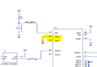
The commented-out line of code that configures the system clock is the code that causes the problem.  The code line that follows, that configures the system clock, works fine and doesn't lock up the controller.  There is a 25MHz oscillator on the board, see attached schematic.  Why would this cause a problem?  Thank you for your time.  

Keller Test Fixture PCB Rev A.pdf

  • Hi,

      The reason is that you do not have an crystal on your custom board. See below image of your schematic. 

    The below clock setup will use the 25Mhz MOSC oscillator as the clock source to the PLL to generate the final 120Mhz system clock. Since you don't have a MOSC then it will not work. 

     SysCtlClockFreqSet((SYSCTL_XTAL_25MHZ |
    SYSCTL_OSC_MAIN |
    SYSCTL_USE_PLL |
    SYSCTL_CFG_VCO_240), 120000000);

    The below call uses the internal 16MHz oscillator as the source to the PLL to generate the system clock. By default, the internal oscillator is used after reset and it will work. Internal oscillator allows customers to save BOM cost but internal OSC may not have the precision compared to the MOSC. It is your application decision to make.

    SysCtlClockFreqSet((SYSCTL_OSC_INT | SYSCTL_USE_PLL |SYSCTL_CFG_VCO_480), 120000000);

  • Charles

    Thank you for the design catch.  This board was designed by another engineer.  However, we all do a peer review on each other's design.  We all missed this one.