This thread has been locked.

If you have a related question, please click the "Ask a related question" button in the top right corner. The newly created question will be automatically linked to this question.

AM2434: Clocking topologies for the receive data capture clock in PHY mode

Part Number: AM2434

Section "7.10.5.14 OSPI" on the datasheet describes the clocking topologies supported for the receive data capture clock.

I understand the clocking topologies supported in PHY mode as follows:

- Internal PHY Loopback: SDR transfers are supported and DDR transfers are NOT supported.
- Internal Pad Loopback: SDR and DDR transfers are NOT supported.
- External Board Loopback: SDR and DDR transfers are supported.
- DQS: SDR transfers are NOT supported and DDR transfers are supported.

Does AM243x support the Internal Pad Loopback clocking topology?

If only DDR transfers are used in PHY mode, which topology is recommended, External Board Loopback or DQS?

I understand the transfer protocols supported by each of the SPI boot modes (OSPI/xSPI/QSPI/SPI) as follows:

- OSPI Boot: 1S-1S-8S
- xSPI Boot: 1S-1S-1S and/or 8D-8D-8D
- QSPI Boot: 1S-1S-4S
- SPI Boot: 1S-1S-1S

Which data capture mode does each of the SPI boot modes (OSPI/xSPI/QSPI/SPI) operate in, PHY mode or TAP mode?

The transfer protocols supported by boot modes operating in PHY mode must also be supported by the clocking topologies.

Best regards,

Daisuke

  • Hi Daisuke-san,

    Does AM243x support the Internal Pad Loopback clocking topology?

    Yes, it does, you can also find additional layout information in section 9.2.3 OSPI/QSPI/SPI Board Design and Layout Guidelines of the datasheet

    If only DDR transfers are used in PHY mode, which topology is recommended, External Board Loopback or DQS?

    This entirely depends on the timing requirements of the memory device you are trying to interface with. If your memory supports a DQS output, you can follow Figure 12-1538. OSPI Connected to an External Octal-SPI Flash Memory of the TRM to communicate with the SOC. Using a DQS topology will allow you enable a source synchronous capture, facilitating timing closure at higher speeds in Octal SPI devices. The External Board Loopback topology serves the same purpose for Quad SPI devices, as DQS is not supported in these devices. 

    If the external memory that you are trying to interface with has very strict/narrow timing values, then the DQS topology in OSPI devices and the External Loopback topology in QSPI devices could help increase the margins on these.

    Which data capture mode does each of the SPI boot modes (OSPI/xSPI/QSPI/SPI) operate in, PHY mode or TAP mode?

    All of them should boot up in TAP mode

    Hope this helps.

    Best,

    Daniel

  • Hi Daniel-san,

    Thank you for your reply.

    Yes, it does, you can also find additional layout information in section 9.2.3 OSPI/QSPI/SPI Board Design and Layout Guidelines of the datasheet

    Section "7.10.5.14 OSPI" on the datasheet describes that both SDR and DDR transfers are NOT supported when using the Internal Pad Loopback clocking topology, is that a typo?

    "SDR transfers are not supported when using the Internal Pad Loopback and DQS clocking topologies."
    "DDR transfers are not supported when using the Internal PHY Loopback or Internal Pad Loopback clocking topologies."

    This entirely depends on the timing requirements of the memory device you are trying to interface with. If your memory supports a DQS output, you can follow Figure 12-1538. OSPI Connected to an External Octal-SPI Flash Memory of the TRM to communicate with the SOC. Using a DQS topology will allow you enable a source synchronous capture, facilitating timing closure at higher speeds in Octal SPI devices. The External Board Loopback topology serves the same purpose for Quad SPI devices, as DQS is not supported in these devices. 

    If the external memory that you are trying to interface with has very strict/narrow timing values, then the DQS topology in OSPI devices and the External Loopback topology in QSPI devices could help increase the margins on these.

    I understand that if the memory device (most OSPI flash) supports DQS output, the DQS clocking topology should be used, and if the memory device (most QSPI flash) does not support DQS output, the External Board Loopback clocking topology should be used.

    All of them should boot up in TAP mode

    Section "4.4.1 OSPI, xSPI, QSPI, SPI Boot" on the TRM describes how to set BOOTMODE8 to use internal iclk or external clock during boot. And sections "4.4.1.1 OSPI Boot" and "4.4.1.3 QSPI Boot" on the TRM describe about the Iclk field of BOOTMODE8 pin.

    Do "OSPI Boot" and "QSPI Boot" boot in PHY mode and "xSPI Boot" and "SPI Boot" boot in TAP mode?

    If only low speed (50 MHz or less) operation is used during boot and normal operation, can the Internal PHY Loopback or the Internal Pad Loopback topology be used?

    When low speed (50 MHz or less) operation is used, are both SDR and DDR transfers supported for all clocking topologies in PHY mode?

    Best regards,

    Daisuke

  • Hi Daniel-san,

    I have several additional questions.

    If SPI/QSPI/OSPI/xSPI boot is used with the memory device which does NOT support DQS output, is only low-speed (50 MHz or less) operation supported?

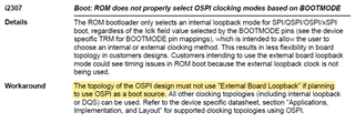
    Advisory i2307 describes that the External Board Loopback clocking topology must not be used since the ROM bootloader only supports an internal loopback mode for SPI/QSPI/OSPI/xSPI boot.

    If the Internal PHY Loopback or Internal Pad Loopback clocking topology is used, is only low-speed (50 MHz or less) operation with SDR transfers supported in PHY mode?

    Advisory i2249 describes that the Internal PHY Loopback and Internal Pad Loopback clocking topologies are not recommended since they are affected by timing inoperable in DDR mode.

    I understand about the clocking topologies supported in PHY mode as follows:

    - Internal PHY Loopback: SDR transfers are supported and DDR transfers are NOT supported. High-speed (>50 MHz) operation is NOT supported.
    - Internal Pad Loopback: This clocking topology is NOT supported since both SDR and DDR transfers are NOT supported.
    - External Board Loopback: SDR and DDR transfers are supported. High-speed (>50 MHz) operation is supported if SPI/QSPI/OSPI/xSPI boot is NOT used.
    - DQS: SDR transfers are NOT supported and DDR transfers are supported. High-speed (>50 MHz) operation is supported.

    However, I am confused by the following descriptions in Section "7.10.5.14 OSPI" on the datasheet.

    "SDR transfers are not supported when using the Internal Pad Loopback and DQS clocking topologies."
    "DDR transfers are not supported when using the Internal PHY Loopback or Internal Pad Loopback clocking topologies."

    If my understanding is incorrect, please correct me.

    Best regards,

    Daisuke

  • Hi Daniel-san,

    Could you first clarify if the following descriptions are correct?

    However, I am confused by the following descriptions in Section "7.10.5.14 OSPI" on the datasheet.

    "SDR transfers are not supported when using the Internal Pad Loopback and DQS clocking topologies."
    "DDR transfers are not supported when using the Internal PHY Loopback or Internal Pad Loopback clocking topologies."

    Please give me an answer as soon as possible. Your prompt reply would be appreciated.

    Best regards,

    Daisuke

  • Hi Daniel-san,

    Sorry for the repeated posts.

    I understand about the clocking topologies supported in PHY mode as follows:

    - Internal PHY Loopback: SDR transfers are supported and DDR transfers are NOT supported. High-speed (>50 MHz) operation is NOT supported.
    - Internal Pad Loopback: This clocking topology is NOT supported since both SDR and DDR transfers are NOT supported.
    - External Board Loopback: SDR and DDR transfers are supported. High-speed (>50 MHz) operation is supported. This clocking topology can NOT be used if SPI/QSPI/OSPI/xSPI boot is used.
    - DQS: SDR transfers are NOT supported and DDR transfers are supported. High-speed (>50 MHz) operation is supported.

    If my understanding is incorrect, please correct me.

    Do all of the SPI/QSPI/OSPI/xSPI boot modes really boot in TAP mode?
    Do "OSPI Boot" and "QSPI Boot" boot in PHY mode and "xSPI Boot" and "SPI Boot" boot in TAP mode?

    I understand about the SPI/QSPI/OSPI/xSPI boot modes as follows:

    Since SDR transfers are not supported when using the Internal Pad Loopback clocking topology:

    The following boot modes cannot be used with the Iclock source internal (pad loopback) in PHY mode.

    - OSPI Boot: 1S-1S-8S
    - QSPI Boot: 1S-1S-4S

    The following boot modes may not be used if it boots in PHY mode instead of TAP mode.

    - xSPI Boot: 1S-1S-1S
    - SPI Boot: 1S-1S-1S

    Since SDR transfers are not supported when using the DQS clocking topology:

    The following boot modes cannot be used with the Iclock source external in PHY mode.

    - OSPI Boot: 1S-1S-8S
    - QSPI Boot: 1S-1S-4S

    Note that it should be used with the Iclock source internal (pad loopback) instead of the Iclock source external.

    The following boot modes may not be used if it boots in PHY mode instead of TAP mode.

    - xSPI Boot: 1S-1S-1S
    - SPI Boot: 1S-1S-1S

    Since DDR transfers are not supported when using the Internal Pad Loopback clocking topology:

    The following boot mode cannot be used with the Iclock source internal (pad loopback) in PHY mode.

    - xSPI Boot: 8D-8D-8D

    If my understanding is incorrect, please correct me.

    Please give me an answer as soon as possible. Your prompt reply would be appreciated.

    Best regards,

    Daisuke

  • Hi Daniel-san,

    Thank you for your support. Our customer is waiting for your answer.

    Please give me an answer as soon as possible. Your prompt reply would be appreciated.

    Best regards,

    Daisuke

  • Hi Daisuke-san,

    I apologize for the lack of replies, I was out of office for two weeks and was unbale to reach my PC. 

    Unfortunately, I do not have an answer to your query right now, I am getting conflicting information on our side regarding the SPI bootmodes. I will reach out to the boot experts to get a clear answer to this, I will get back to you as soon as I have an answer and no later than Monday.

    Thank you for your patience on this.

    Best,

    Daniel

  • Hi Daniel-san,

    Thank you for your reply.

    I would like to know if the following description in Section "7.10.5.14 OSPI" on the datasheet is correct.

    "SDR transfers are not supported when using the Internal Pad Loopback and DQS clocking topologies."

    I would like to clarify which data capture mode (PHY or TAP mode) each of the SPI/QSPI/OSPI/xSPI boot modes operates in.

    Please give me an answer as soon as possible. Your prompt reply would be appreciated.

    Best regards,

    Daisuke

  • HI Daisuke-san,

    I was able to get comment from the experts.

    I would like to know if the following description in Section "7.10.5.14 OSPI" on the datasheet is correct.

    Your assumptions and datasheet are correct, neither DDR or SDR modes are supported in Internal Pad Loopback topology. Internal Pad Loopback is actually not supported on AM243x.

    I would like to clarify which data capture mode (PHY or TAP mode) each of the SPI/QSPI/OSPI/xSPI boot modes operates in.

    All the boot modes described above boot only on non-PHY mode and use TAP delay.  All boot modes (SPI, QSPI, OSPI and XSPI) search 16 values of the read delay parameter to determine the best value for read. This procedure is currently not highlighted anywhere, but we will be working on a document that will go over the specifics of these bootmodes.

    Hope this helps.

    Best,

    Daniel

  • Hi Daniel-san,

    Thank you for your reply.

    "SDR transfers are not supported when using the Internal Pad Loopback and DQS clocking topologies."

    Why are SDR transfers not supported when using the DQS clocking topology?

    Is that planned to be supported in future?

    Section "4.4.1 OSPI, xSPI, QSPI, SPI Boot" on the TRM describes how to set BOOTMODE8 to use internal iclk or external clock during boot. And sections "4.4.1.1 OSPI Boot" and "4.4.1.3 QSPI Boot" on the TRM describe about the Iclk field of BOOTMODE8 pin.

    For OSPI boot and QSPI boot, is the Iclk field of BOOTMODE8 pin ignored and operated in TAP mode?

    Advisory i2307 describes that the External Board Loopback clocking topology must not be used since the ROM bootloader only supports an internal loopback mode for SPI/QSPI/OSPI/xSPI boot.

    I understand Advisory i2307 does not apply for TAP mode.

    Does Advisory i2307 not apply for the SPI/QSPI/OSPI/xSPI boot modes?

    Can the External Board Loopback clocking topology be used even if one of the SPI/QSPI/OSPI/xSPI boot modes is used?

    Best regards,

    Daisuke

  • Daisuke-san,

    Why are SDR transfers not supported when using the DQS clocking topology?

    Is that planned to be supported in future?

    As of now it looks like the topology either did not get verified or may not have been timing closed. I am unsure if there are plans to support it in the future

    For OSPI boot and QSPI boot, is the Iclk field of BOOTMODE8 pin ignored and operated in TAP mode?

    ROM bootloader only operates at low speeds. It was already confirmed that all the above bootmodes come up in TAP mode. Advisory i2307 also seems to confirm that the value of Iclk would be irrelevant in OSPI and QSPI bootmodes as it confirms that the ROM bootloader only selects an internal loopback mode for SPI/QSPI/OSPI/xSPI bootmodes.

    Does Advisory i2307 not apply for the SPI/QSPI/OSPI/xSPI boot modes?

    External board loopback should be supported in TAP mode, I will double check on this and get back to you.

    For now, does this help with your previous two questions? 

    Best,

    Daniel

  • Hi Daniel-san,

    Thank you for your reply.

    I understand that the internal clock is used in TAP mode, so the clock topology is irrelevant and any clock topology can be used even if the SPI/QSPI/OSPI/xSPI boot is used, is that correct?

    Best regards,

    Daisuke

  • Daisuke-san,

    so the clock topology is irrelevant and any clock topology can be used even if the SPI/QSPI/OSPI/xSPI boot is used, is that correct?

    If we are strictly talking about boot operation, then yes, clocking topology would be irrelevant as ROM bootloader only uses the internal clock at boot in TAP mode (in all modes in fact) despite the Iclk value selected.

    However, the notes about Iclk in section 4.4.1 OSPI, xSPI, QSPI, SPI Boot also apply to normal operation: 

    "–To support high-speed OSPI with the DQS signal during normal operation, set BOOTMODE8=1 to use internal iclk during boot and ensure signal LBCLKO is a no connect (that is, absolutely no trace can be connected to LBCLKO). The ROM boot operates OSPI at low speed (50 MHz), and during normal operation the OSPI interface can use the DQS signal to operate the interface at high speeds."

    " –To support only low-speed OSPI\xSPI\QSPI\SPI operation (that is, <=50-MHz OSPI clock), set BOOTMODE8=1 to use internal iclk, and ensure signal LBCLKO is a no connect (that is, absolutely no trace can be connected to LBCLKO). Operation for both ROM boot and normal operating mode clock the interface at low speed and use the internally pad looped back clock. The DQS and LBCLKO signals are not used during boot or normal operation"

    In this case "normal" operation refers to operation after boot. So that leaves us with Internal Pad loopback being the only one supported at boot but not being supported at normal operation (neither SDR nor DDR work with this topology), and External Board Loopback not being supported at boot time but being supported at normal operation to close at higher speeds. 

    Best,

    Daniel

  • Hi Daniel-san,

    Thank you for your reply.

    External Board Loopback not being supported at boot time but being supported at normal operation to close at higher speeds

    Does that mean that when using the External Board Loopback clock topology, the internal clock is used in TAP mode during boot and the looped back clock can be used in PHY mode during normal operation?

    I understand about the clocking topologies supported in PHY mode as follows:

    - Internal PHY Loopback: SDR transfers are supported and DDR transfers are NOT supported. High-speed (>50 MHz) operation is NOT supported.
    - Internal Pad Loopback: This clocking topology is NOT supported since both SDR and DDR transfers are NOT supported.
    - External Board Loopback: SDR and DDR transfers are supported. High-speed (>50 MHz) operation is supported.
    - DQS: SDR transfers are NOT supported and DDR transfers are supported. High-speed (>50 MHz) operation is supported.
    And any clock topology can be used except the Internal Pad Loopback since the internal clock is used in TAP mode for SPI/QSPI/OSPI/xSPI boot modes.

    If my understanding is incorrect, please correct me.

    If there are any restrictions for SPI/QSPI/OSPI/xSPI boot modes, could you tell me what they are?

    Best regards,

    Daisuke

  • Daisuke-san, 

    It has come to my attention that our documentation is not making clear distinction on at what times these different modes of operation are supported and when not. I can't give you an answer right now since there are multiple discussions on our side regarding this. Expect an answer no later than Tuesday on this thread.

    Thank you for your patience on this query 

    Best,

    Daniel

  • Hi Daniel-san,

    Thank you for your support.

    Please give me an answer as soon as possible. Your prompt reply would be appreciated.

    Best regards,

    Daisuke

  • Hi Daisuke-san,

    We came up with the following Summary tables for the device:

    I hope this helps answer your question.

    Best,

    Daniel

  • Hi Daniel-san,

    Thank you for your reply.

    I understand that any clock topology except the Internal Pad Loopback can be used to design for normal operation even if the SPI/QSPI/OSPI/xSPI boot is used since the internal clock is used in TAP mode for all of those boot modes, is that correct?

    Can the SPI/QSPI/OSPI/xSPI boot be used when designing with the External Board Loopback?

    Best regards,

    Daisuke

  • Hi Daisuke-san

    I understand that any clock topology except the Internal Pad Loopback can be used to design for normal operation even if the SPI/QSPI/OSPI/xSPI boot is used since the internal clock is used in TAP mode for all of those boot modes, is that correct?

    In normal operation yes, assuming you use a different bootmode other than SPI/QSPI/OSPI/xSPI.

    You will not be able to use the external board loopback topology if you are using SPI/QSPI/OSPI/xSPI bootmodes since LBCLKO has to be a no connect to ensure correct boot operation at slow speed. This is also what advisory i2307 concludes:

    Best,

    Daniel

  • Hi Daniel-san,

    Thank you for your reply.

    I understand that if Advisory i2307 is correct, TAP mode cannot be used even in normal operation when designed with External Board Loopback, is that correct?

    Best regards,

    Daisuke

  • Hi Daisuke-san,

    TAP mode only works with no loopback. If you use External Board loopback you won't be able to use TAP mode since no trace should be connected on LBCLKO for No Loopback to work.

    If you want to use External Loopback topology you won't be able to use the SPI/QSPI/OSPI/xSPI bootmodes since they only work in Tap mode

    Best,

    Daniel

  • Hi Daniel-san,

    Thank you for your reply.

    I understand that PHY mode is used only for read data and TAP mode is used for others, as discussed in the thread here:

    e2e.ti.com/.../am2434-maximum-clock-frequency-for-ospi-flash

    If so, I understand that the External Board loopback clock topology cannot be used for AM243x, is that correct?

    Best regards,

    Daisuke

  • Hi Daisuke-san,

    There is no reason why the PHY can't be used for both reads and writes. TX and RX are both supported in the Phy mode of operation. The post you referenced may be constrained to SDK as it is not representative of everything you can do with the IP.

    My answer to your question is still the same as before. External Board loopback is supported in normal operation as long as you don't use the SPI/QSPI/OSPI/xSPI bootmodes, which are limited to boot in Tap mode, which is limited to No Loopback topology

    Best,

    Daniel

  • Hi Daniel-san,

    Thank you for your reply.

    I understand about the clocking topologies supported in PHY mode as follows:

    - Internal PHY Loopback: SDR transfers are supported and DDR transfers are NOT supported. High-speed (>50 MHz) operation is NOT supported.
    - Internal Pad Loopback: This clocking topology is NOT supported since both SDR and DDR transfers are NOT supported.
    - External Board Loopback: SDR and DDR transfers are supported. High-speed (>50 MHz) operation is supported. This clocking topology can NOT be used if TAP mode is used. This clocking topology can NOT be used if the SPI/QSPI/OSPI/xSPI boot modes are used since the boot modes are limited to boot in TAP mode.
    - DQS: SDR transfers are NOT supported and DDR transfers are supported. High-speed (>50 MHz) operation is supported.

    If my understanding is incorrect, please correct me.

    Best regards,

    Daisuke

  • Hi Daisuke-san,

    This information is aligned with our understanding and documentation, we will make sure this is clearer in the future as well. 

    Best,

    Daniel