This thread has been locked.

If you have a related question, please click the "Ask a related question" button in the top right corner. The newly created question will be automatically linked to this question.

MCU-PLUS-SDK-AM263X: MCU-PLUS-SDK-AM263X

Part Number: MCU-PLUS-SDK-AM263X
Other Parts Discussed in Thread: SYSCONFIG

Hi,

May I know:

1, May I know if I can select anyone instance if I used only core0?

2, What is the map of intr_num with instance since I'd like ti register ISR? 

in this example,

GPIO Pins in AM263x:

AM263x has 139 GPIO pins

The device has four instances of the GPIO module, one dedicated per R5FSS processor core

  • Pinmux/IOMUX allows assignment of GPO pin control to a specific R5FSS processor core using a 4:1 MUX  (MCUSDK sysconfig generates code automatically for configuring this)
  • GPI pins are observable by all processor cores

The GPIO modules are capable of supporting a maximum of 144 dedicated pins. AM263x implements 139 pins.

GPIO Interrupts in AM263x:

Regarding interrupts,

From the GPIO modules, 180 events/interrupts reach as input to GPIO Interrupt XBAR as shown in diagram below. 

The 180 inputs contain both the individual GPIO interrupts (144 muxed from 4 GPIO modules) and also the 9 bank interrupts of 4 GPIO module

  Number of Interrupts
Single GPIO Pin Interrupts 144
GPIO Bank Interrupts for instance 0 9
GPIO Bank Interrupts for instance 1 9
GPIO Bank Interrupts for instance 2 9
GPIO Bank Interrupts for instance 3 9
Total Interrupts  180

In the Current SDK 8.5 we have gpio_input_interrupt example using GPIO bank interrupt.

In the example Go to SysCfg --> GPIO INT XBAR Option.

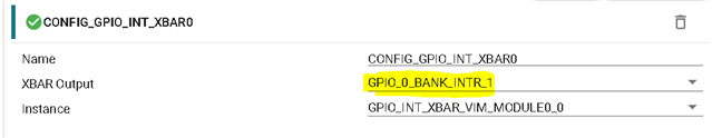
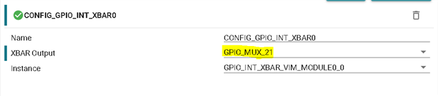
To use the Individual GPIO Interrupt, change the XBAR Output option to respective GPIO_MUX pin required for you. Here ignore the "_MUX" in this context, this refers to the individual GPIO Pin only.

While acknowledging and checking the interrupt status for Individual and Bank GPIO Interrupts these APIs can be used:

GPIO Bank Individual GPIOs
GPIO_getBankIntrStatus GPIO_getIntrStatus
GPIO_clearBankIntrStatus GPIO_clearIntrStatus

  • Hi 

    1, May I know if I can select anyone instance if I used only core0?

    Core 0 gets interrupts serviced from VIM 0 Module. And you Can service upto 4 external gpio interrupts to VIM.

    Core 0: ---> VIM0  ---> VIM0_0

                                 ---> VIM0_1

                                ----> VIM0_2

                                ----> VIM0_3

    So you can select any of these instances.

    By default VIM0_0 instance is selected in the gpio_interrupt SDK example.

  • Hi

    2, What is the map of intr_num with instance since I'd like ti register ISR?

    The instances map is available in syscfg --> go to INT XBAR --> when no module is added, you can see the map here.

    The image is too big so I had to crop and place it here, So I would request you to look it into the Syscfg itself.

    There are interrupt controller maps for different modules in the TRM Interrupt section and GPIO section also.

    Could you please look at these and let me know if this answers your query. If you think some other map would be useful do let me know I will try to get it from the internal teams.

    Thanks & regards

    Sri Vidya

  • Thanks,

    I got it.

    Suven

  • Dear Sri Vidya,

      "By default VIM0_0 instance is selected in the gpio_interrupt SDK example."

    GPIO_INT_XBAR_VIM_MODULE0_0 is selected in instance option and its intr_num is 142.

    I'd like to know the intr_num map of the others. Totoal is 30.

    Thanks

    Suven


  • Hi Suven

    The above map already explains it.

    Here x4 for VIM0 represents that there are 4 external interrupts possible from GPIO to that particular end peripheral, VIM0 in this case.

    4 is the XBAR Outputs possible

    Right side peripherals are the instances.

    The possible XBAR outputs you can see by clicking on the drop down in syscfg, similarly for the instances also you can click on the drop down and check.

    Thanks & Regards

    Sri Vidya

  • Hi 

    simply the question.

    what's the intr_num of GPIO_INT_XBAR_SOC_TIMESYNC_XBAR1_0? Is it "10"?

    what's the intr_num of GPIO_INT_XBAR_SOC_TIMESYNC_XBAR1_1? Is it "11"?

    what's the intr_num of GPIO_INT_XBAR_SOC_TIMESYNC_XBAR1_2? Is it "12"?

    ...

    I'd like to know their intr_num.

    Thanks

    Suven

  • Hi 

    I get your question now. All these values are available in the SDK. You can add the SDK in any folder representation workspace like VS Code and look for the macros and driver code.

    SDK default path: C:\ti\mcu_plus_sdk_am263x_08_05_00_24

    For the interrupt CrossBar numbers you asked, these are the numbers defined in the SDK:

    File path: C:\ti\mcu_plus_sdk_am263x_08_05_00_24\source\drivers\hw_include\am263x\cslr_gpio_intr_xbar.h

    Thanks & regards

    Sri Vidya

  • Hi,

    In the example of gpio_input_interrupt.

    It registers GPIO_bankIsrFxn() with the intrNum that return from Board_getGpioButtonIntrNum().

    It is 142 actually.

    It means the intr_num is 142 for GPIO_INT_XBAR_VIM_MODULE0_0 instance.

    And I know the intrl_num is 143,144 and 145 for GPIO_INT_XBAR_VIM_MODULE0_1,2 and 3 from my experiment.

    What is the intr_num for below? 

    Thanks

    Suven

  • Hi,

    The 144, 145, etc values are the interrupt sources for core0_0.

    path: C:\ti\mcu_plus_sdk_am263x_08_05_00_24\source\drivers\hw_include\am263x\cslr_intr_r5fss0_core0.h

    For the INT Xbar, we also configure the output instance

    Its done through this API: 

    /*
    * GPIO INTERRUPT XBAR
    */
    SOC_xbarSelectGpioIntrXbarInputSource(CSL_GPIO_INTR_XBAR_U_BASE, GPIO_INT_XBAR_VIM_MODULE0_0, GPIO_INT_XBAR_GPIO_MUX_23);

    This is where you configure the instance for which your Interrupt is serviced.

    Thanks & Regards

    Sri Vidya

  • Hi,

    again,

     142 is the intrNum of GPIO_INT_XBAR_VIM_MODULE0_0 output instance. 

    143 is the intrNum of GPIO_INT_XBAR_VIM_MODULE0_1 output instance.

     144 is the intrNum of GPIO_INT_XBAR_VIM_MODULE0_2 output instance.

     145 is the intrNum of GPIO_INT_XBAR_VIM_MODULE0_3 output instance.

    What are their intrNum of bleow? Where I can find them?

    GPIO_INT_XBAR_ICSS_XBAR_0

    GPIO_INT_XBAR_ICSS_XBAR_1

    GPIO_INT_XBAR_ICSS_XBAR_2

    GPIO_INT_XBAR_ICSS_XBAR_3

    GPIO_INT_XBAR_DMA_TRIG_XBAR_0

    GPIO_INT_XBAR_DMA_TRIG_XBAR_1

    GPIO_INT_XBAR_DMA_TRIG_XBAR_2

    GPIO_INT_XBAR_DMA_TRIG_XBAR_3

    GPIO_INT_XBAR_SOC_TIMESYNC_XBAR1_0

    GPIO_INT_XBAR_SOC_TIMESYNC_XBAR1_1

    GPIO_INT_XBAR_SOC_TIMESYNC_XBAR1_2

    GPIO_INT_XBAR_SOC_TIMESYNC_XBAR1_3

    GPIO_INT_XBAR_SOC_TIMESYNC_XBAR1_4

    GPIO_INT_XBAR_SOC_TIMESYNC_XBAR1_5

    Thanks

    Suven

  • Hi Suven

    Will get back to you soon on this.

    Thanks & Regards

    Sri Vidya

  • Hi Suven

    The GPIO INT XBAR when routed to VIM0_0, it gives an interrupt to the R5 core. Hence R5 is being configured with interrupt number.

    But for other instances like DMA and ICSS, the interrupt XBAR is routed to those respective peripherals. And these wont be coming to the R5 core to handle them. Hence there isnt any interrupt number for other instances. More information on these is mentioned in the 10.3 Interrupt Routers and  10.3.2 INTRTR Integration section of TRM.

    Regards

    Sri Vidya

  • Thanks Sri Vidya.