This thread has been locked.

If you have a related question, please click the "Ask a related question" button in the top right corner. The newly created question will be automatically linked to this question.

AM2431: MCU_OSC0 Crystal Circuit Requirements

Part Number: AM2431

Hi Team,

1)

in table 7-17. page 145 of AM2431 DS there is stated CL should be between 6 and 12 pF. 

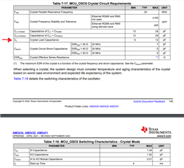
Is this CL the external capacitors ( CL=CL1 = CL2)? or is this the load capacitance from quarz datasheet? or is this CL =  ?

2) Second question regarding the calculation of CL (Cload)

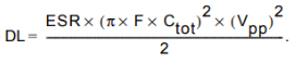
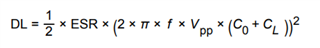
in DS of AM2431 the following equation is used 

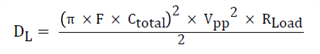
while in lot of other documentation including SNLA290 the following equation is used 

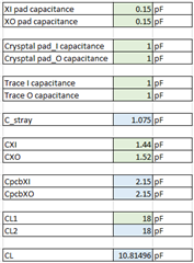
if we use CXI = 1.44pF , CXO = 1.52pF, Cpin = CXI+ CXO = 2.96pF

and CpcbXI = 1pF , CpcbXO = 1pf,  Cstray = CpcbXI + CpcbXO = 2pF

and use CL1 = CL2 = 10pF

with first equation we get from AM2341 Ds we get CL = 6.24pF, and with second equation we get 9.96pF the difference is 3.72pF

Which equation is more accurate?

Because if i select crystal eg 10pF  https://www.raltron.com/webproducts/specs/CRYSTAL/RH100-25.000-10-F-3030-TR-NS2.pdf

with first equation i have to use 18pf external capacitors and with second equation i have to use 10pF external capacitors

Best Regards,

d.

  • Hi, 

    CL is intended to denote the total load capacitance seen by the crystal. Our crystal amplifier circuit can handle the range of CL specified in the datahseet. 

    I tried to summarize all of these questions in a AM263x crystal selection guide. Same applies for the AM243x, but with its own datasheet limits applied. Please reference the attached PDF and let me know if you have any additional questions. I will get this info into the AM243x and the AM263x Hardware Design Guides for easy reference later. 

    0820.AM263x_Crystal_Selection_rev1.pdf

    Thank you,

    -Randy

  • Hi Randy,

    thank you for the additional document.

    Based on the DS specification that CL should be between 6 and 12 pF we will go with Crystal that has CL=10pF.

    eg. ECS-250-10-33B-CWN-TR ( ESR 40Ohm)

    Here are my calculation ( Green input field, blue calculated field)

    CL = [(CL1 + CPCBXI + CXI) × (CL2 + CPCBXO + CXO)] / [(CL1 + CPCBXI + CXI) + (CL2 + CPCBXO + CXO)]

    CpcbXI = (XI pad capacitance + Crysptal pad_I capacitance + Trace I capacitance)

    CpcbXo = (XO pad capacitance + Crysptal pad_O capacitance + Trace O capacitance) 


    I selected Cl1=CL2 = 18pF

    CL1 + CpcbXI = 18 + 2.15 = 20.5pF < 24pF as stated in DS, came for CL2 + CpcbXO

    ESR = 40, below 50Ohm

    Cshunt 3.05pF is below 5pf Sa stat4ed in DS

    Questions:

    1) I assume that the 24pF max in DS comes form the graph similar to the graph in figure 4 SNLA290 

    Can you provide similar graph for AM2431 or the gM of the amplifier ( Eg 2 in SNLA290)

    2) Crystal Drive Level

    Can you provide formula for drive level estimation without measuring the Irms through the crystal?

    Is the formula in 7.11.4.1.2 ok only for the AM2431 ?

    if yes can you explain what are the factors 0.5 and 1.8 in the equation ?

    Other formulas also use not oly CL but CL +Co ( shunt capacitance) , please comment?

    3) Drive level Rs calculation

    if using this equation with ESR=40Ohm and F = 25MHz and CL =10pF , i get 160uW

    if using equation with Co= 3pF then i get 270uW

    would you suggest to use crystal series resistor and calculate it  by following equation from SNLA190

     or should i add to CLA also the CpcbXO + CXO?

    with only CL2 i get 354 Ohm, and if parasitic added then i set ~ 300 Ohm

    4) This Rs of 300Ohm now effects the on Rneg and will reduce the negative resistance margin

    an in order to evaluate this we need the graph or the gm parameter.

    as per SLLA549 eq 32,33,34

    Best Regards,

    d.

  • Hi Randy,

    any comment on the above questions?

    Br,

    d.

  • Hi, 

    I don't see a problem with your crystal selection. On the additional questions you had: 

    1. The DS crystal specification limits are design constraints based on similar analysis, but I do not have those additional graphs to provide. 

    It sounds like this the purpose of this question to better understanding the operating margin of a particular component selection vs. our crystal circuit limits? The datasheet limits have necessary design margin already baked in, so as long as the components stay within or at those limits, the device will operate. 

    2., 3. and 4. Similar to Q1, I do not have additional drive level numbers to share either. 

    -Randy

  • Hi Randy,

    do you see any problem using a 100uW (ECS-250-10-37B2-CWN)  max DL crystal with AM2431

    ESR=50Ohm

    Cload=10pF

    Co=3pF

    Best Regards,

    d.

  • Hi d, 

    I don't see anything wrong with it from our datasheet requirements. But I do see that the crystal datasheet lists a separate drive level specification. I'll check on that and get back to you. 

    -Randy

  • Hi d., 

    I haven't figured out the best way to completely document this, but with the max 50 ohm ESR we support, our crystal oscillator circuit should result in a max DL < 18uW. So your 100uW requirement is easily met. 

    Thank you,

    -Randy

  • Hi Randy,

    1)

    if we use the DL equation from 0820.AM263x_Crystal_Selection_rev1.pdf

    And use

    ESR=50Ohm

    Fxtal= 25MHz

    CL= 10pF + 3pF ( Load Capacitance + Shunt Capacitance from Crystal Datasheet )

    we get DL = 337.4uW

    Can you explain ?

    2)

    On the other side, there is following equation from ECS

    Where 

    ESR= 50Ohm

    F=25MHz

    Ctot = CL1 +Cstray/2 = 18pF + 2pF/2 = 19pF

    Vpp =1.8V

    DL= 180.2uW

    But they say that Vpp is not 1.8V but mush less below 1V, then DL ( 1V) = 55uW

    3) Similar equation (EQ 26) is also used in SLLA249 but the Ctoal is calculated as ( Load Capacitance + Shunt Capacitance from Crystal Datasheet )

    Rload = ESR=50Ohm

    F=25MHz

    Vpp=1.8V

    Ctotal= 10pF + 3pF = 13pF

    DL= 85uW

    This equation DL is below 100uW :)

    ------------------------------------------------------------------------------

    Please can we have your comments?

    Best Regards,

    d.

  • Let me look at this and get an answer back this week. 

    -Randy

  • In the case of AM243x, the current is limited to around 600uA and (outside of startup) and oscillator amplitude is targeted at 1.0V. P = ESR * I^2 = 50 ohm * (600uA)^2 = 18uW.

    Due to this current limiting and oscillation amplitude control the maximum output power from our crystal amplifier would be limited to around 18uW. 

    I'd need to work through our power calculation equation as well to verify that DL equation is applicable, but I am sure our limiting case would be around 18uW. 

    Thank you,

    -Randy