This thread has been locked.

If you have a related question, please click the "Ask a related question" button in the top right corner. The newly created question will be automatically linked to this question.

LP-MSPM0L1306: GPIO

Part Number: LP-MSPM0L1306
Other Parts Discussed in Thread: MSPM0L1306, SYSCONFIG
  1. We are using the LP_MSPM0l1306 development board,We flashed the example code which is given as source code.
  2. In which the GPIO program is working fine,for given pin only as it is already defined in the (ti_msp_config.h) header file.
  3. We need to work with other pins as well,But we worked with those pins but could not get the expected output.
  4. In source code it is given like this (DL_GPIO_clearPins(GPIO_LEDS_PORT, GPIO_LEDS_USER_LED_2_PIN);)  and it is working fine,If we changed like this for the same pin in different mode (DL_GPIO_togglePins(GPIOA,DL_GPIO_PIN_26);) it is working fine.

       But if we write as  (DL_GPIO_togglePins(GPIOA,DL_GPIO_PIN_0) like this it is not working but it is compiling without any error.


        Kindly help us to use the other GPIO pins for user defined I/O

  • Hi Mohankumar,

    If your Pin0 is for PA0 then you would need pull-ups because it is an open drain IO pin. I would suggest switching to use PA3 and let me know if you are experiencing the same.

    Regards,

    Luke

  • Hi Luke Ledbetter,

                          I used PA3 pin to toggle the led and I am not getting the output.So kindly let us know what we should do to come out of this issue.


  • Hi Mohankumar,

    I imported and used the gpio_toggle_output example code and in Sysconfig just added another GPIO with the pin on PA3. For the code I just added GPIO_GRP_0_PIN_0_PIN to the set pins function on line 43. PA3 isn't connected to the LED so you won't visually be able to see it change unless you attach a scope or look at it with a multimeter.

    If you wanted to use PA0 instead since it is an Open Drain IO we do have pull-ups on the board. If you have J10 populated it is routed to pull up the PA0 pin. This will allow you to toggle/set PA0 and see the output on LED D2.

    If you have further trouble can you send your code snippet and a screenshot of the Sysconfig section for GPIO and the selected PinMux.

    Regards,

    Luke

  • screenshot of the Sysconfig section for GPIO and the selected PinMux.

    Hi Luke,

       We could toggle the LED in PA3 pin and other pins as well.Now we are working with ADC module,in the attached program gADCResult is 0x7ff is there.

    We used 1kohm potentiometer to adjust a adc voltage,once the code is uploaded LED is turned on but it is not turning off when we change the adc voltage using potentiometer ,But instead if we assign 0x001 for gADCResult the brightness of the LED_D2 is changing gradually.Kindly help us to use the(0x7ff) value.

    int main(void)
    {
    SYSCFG_DL_init();

    NVIC_EnableIRQ(ADC12_0_INST_INT_IRQN);
    gCheckADC = false;

    while (1) {
    DL_ADC12_startConversion(ADC12_0_INST);

    while (false == gCheckADC) {
    __WFE();
    }

    gAdcResult = DL_ADC12_getMemResult(ADC12_0_INST, DL_ADC12_MEM_IDX_0);

    if (gAdcResult > 0x7ff)
    //if (gAdcResult > 0x001)
    {
    DL_GPIO_setPins(GPIO_LEDS_PORT, GPIO_LEDS_USER_LED_1_PIN);
    } else {
    DL_GPIO_clearPins(GPIO_LEDS_PORT, GPIO_LEDS_USER_LED_1_PIN);
    }
    gCheckADC = false;
    DL_ADC12_enableConversions(ADC12_0_INST);
    }
    }

  • Hi Mohankumar,

    This is directly the adc12_single_conversion example. I've tested this and it works on my end by connecting the potentiometer with one end to GND, the other end to 3.3V and the middle going to PA25. Since the to check value is 0x7FF, it is half the FSR so if the voltage is greater than 1.65V then the LED will be on and if its less than 1.65V the LED should turn off (The example uses VDD as reference). I wouldn't expect this example to be able to do any change in the brightness as it is just turning on or off the GPIO, which would produce a single value for voltage/current.

    If your LED is consistently on then I believe that you would have a voltage above 1.6V. Are you using a breadboard setup? I would recommend connecting a scope or use a multimeter to get what the voltage out is, there could be a short if you are using a breadboard.

    Regards,

    Luke

  • Hi Luke,

    I am using a LP_MSPM0L1306 development board in which I have taken PA25.I selected adc12_single_conversion internal reference  example. I have  connected the potentiometer with one end to GND, the other end to 3.3V and the middle going to PA25. I used 10bit ADC resolution so I check the adcresult value with 0x200(which is equal to 1.65V).when the voltage is higher than the check voltage(i.e 1.65V) LED has to turned on,But it is not turning on,if we debug it stuck in this line(while (false == gCheckADC)).So kindly help us to find this issue.

  • Hi Mohankumar,

    I tested the code just by changing the example from 12 bits to 10 bits in Sysconfig, and changing the check from 0x7ff to 0x200. I used a potentiometer but you can also connect a jumper from PA25 to the 3.3V that is next to it. By doing this you can verify that the jumpers are correctly populated otherwise the LED won't turn on (or will be very faint).

    Do you have J4 unpopulated? This is on the light sensor section on the bottom left of the board. If this is populated it will short your connection on PA25 to ground. 

    Regards,

    Luke

  • Dear Luke,        
       
    As you replied PA.25 is connected with ground through J4. We got the expected output after we removed Jumper (J4).We tried with PA15,PA27 these two pins to find the ADC output by the same procedure what we followed for the PA25 pin.But we could not get the output.We removed the respective jumper to the pins.We could not modify ADC Pinmux  Peripheral  and pin configuration in sysconfig for ccs IDE.Kindly reply as soon as possible.
  • Hi Mohankumar,

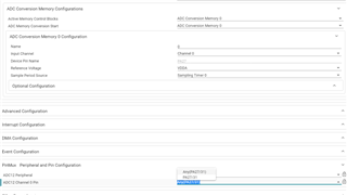
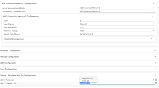
    To change the ADC pins you will need to change the channel that is associated to the Conversion Memory configuration, these can't be changed directly through the PinMux tab.

    Channel 0 shown below is associated with pin 31/ PA27

    Channel 2 shown below is associated with pin 29/ PA25

    The jumpers that will need to be removed are J1 (the thermistor circuit) and J13 (RGB LED circuit). Are you trying to sample all of these or were you checking them one at a time? 

    Regards,

    Luke

  • Hi Luke, 

               We already tried to get one sample at a time.We removed the J1 and J13 jumper to get adc output in PA15 and PA27 pins respectively.But we did not get  the expected output.

  • Hi Mohankumar,

    Can you send me a picture of your launchpad setup and a screenshot of your Sysconfig for the ADC section?

    Regards,

    Luke

  • Reg image.zip

    Hi Luke,

          We are attached the Launchpad  setup image and sysconfig for the ADC screenshot for your reference.kindly check and revert as soon as possible.

    Regards,

    LAVANYA M,
    Associate - Software Engineer,
    Roots Industries India Ltd.,
    Ganapathy, Coimbatore -641006.
    Phone:+91 422 4330362

  • Hello,

    If you used the example code you will want "repeat mode" unchecked. Once I unchecked this the program worked as expected. 

    or

    Adjust your code to below. In the ISR I added, DL_ADC12_disableConversions(ADC12_0_INST); This allows the CPU to execute the rest of the code, otherwise it keeps getting interrupted by the ADC.

    m/*
     * Copyright (c) 2020, Texas Instruments Incorporated
     * All rights reserved.
     *
     * Redistribution and use in source and binary forms, with or without
     * modification, are permitted provided that the following conditions
     * are met:
     *
     * *  Redistributions of source code must retain the above copyright
     *    notice, this list of conditions and the following disclaimer.
     *
     * *  Redistributions in binary form must reproduce the above copyright
     *    notice, this list of conditions and the following disclaimer in the
     *    documentation and/or other materials provided with the distribution.
     *
     * *  Neither the name of Texas Instruments Incorporated nor the names of
     *    its contributors may be used to endorse or promote products derived
     *    from this software without specific prior written permission.
     *
     * THIS SOFTWARE IS PROVIDED BY THE COPYRIGHT HOLDERS AND CONTRIBUTORS "AS IS"
     * AND ANY EXPRESS OR IMPLIED WARRANTIES, INCLUDING, BUT NOT LIMITED TO,
     * THE IMPLIED WARRANTIES OF MERCHANTABILITY AND FITNESS FOR A PARTICULAR
     * PURPOSE ARE DISCLAIMED. IN NO EVENT SHALL THE COPYRIGHT OWNER OR
     * CONTRIBUTORS BE LIABLE FOR ANY DIRECT, INDIRECT, INCIDENTAL, SPECIAL,
     * EXEMPLARY, OR CONSEQUENTIAL DAMAGES (INCLUDING, BUT NOT LIMITED TO,
     * PROCUREMENT OF SUBSTITUTE GOODS OR SERVICES; LOSS OF USE, DATA, OR PROFITS;
     * OR BUSINESS INTERRUPTION) HOWEVER CAUSED AND ON ANY THEORY OF LIABILITY,
     * WHETHER IN CONTRACT, STRICT LIABILITY, OR TORT (INCLUDING NEGLIGENCE OR
     * OTHERWISE) ARISING IN ANY WAY OUT OF THE USE OF THIS SOFTWARE,
     * EVEN IF ADVISED OF THE POSSIBILITY OF SUCH DAMAGE.
     */
    
    #include "ti_msp_dl_config.h"
    
    volatile bool gCheckADC;
    volatile uint16_t gAdcResult;
    
    int main(void)
    {
        SYSCFG_DL_init();
    
        NVIC_EnableIRQ(ADC12_0_INST_INT_IRQN);
        gCheckADC = false;
    
        while (1) {
           DL_ADC12_startConversion(ADC12_0_INST);
    
            while (false == gCheckADC) {
                __WFE();
            }
    
            gCheckADC = false;
            gAdcResult = DL_ADC12_getMemResult(ADC12_0_INST, DL_ADC12_MEM_IDX_0);
    
            if (gAdcResult > 0x200) {
                DL_GPIO_setPins(GPIO_LEDS_PORT, GPIO_LEDS_USER_LED_1_PIN);
            } else {
                DL_GPIO_clearPins(GPIO_LEDS_PORT, GPIO_LEDS_USER_LED_1_PIN);
            }
            DL_ADC12_enableConversions(ADC12_0_INST);
        }
    }
    
    void ADC12_0_INST_IRQHandler(void)
    {
        switch (DL_ADC12_getPendingInterrupt(ADC12_0_INST)) {
            case DL_ADC12_IIDX_MEM0_RESULT_LOADED:
                gCheckADC = true;
                DL_ADC12_disableConversions(ADC12_0_INST);
                break;
            default:
                break;
        }
    }
    

    Regards,

    Luke

  • Hi Luke,


                                  We are faced with uploading the code via USB cable, earlier we followed the same method to upload the code and suddenly it doesn't work.

    Error screenshot image is also attached. Please help us.


  • Hi Luke,


    We are facing issue when uploading the code via USB cable, earlier we followed the same method to upload the code and suddenly it doesn't work.

    Error screenshot image is also attached. Please help us.

  • Hi Mohankumar,

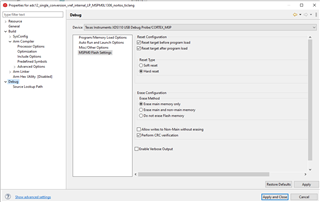
    Can you verify that you are not using a low power mode and that you are erasing main memory only.

    Low Power mode should be on Sleep0

    Right Click Project, go to project properties -> debug -> MSPM0 Flash Settings.

    To recover the device you will need to invoke the BSL.

    Hold NRST and S1(PA18) then press the debug button on CCS. CCS will build the project, once the first pop up appears release NRST then S1. Further recovery options are in MSPM0_Known_Issues_FAQ 

    Regards,

    Luke

  • Hi Luke,

                     We have attached image file of pwm with change of duty,we would like to generate  PWM with different duties which changes gradually with respect to ADC input and need to on and off for 500ms respectively using a timer.Since it is sysconfig we cannot modify in the loop  .


    So kindly help us