This thread has been locked.

If you have a related question, please click the "Ask a related question" button in the top right corner. The newly created question will be automatically linked to this question.

TMDSEMU110-U: Recently adquired probe unable to run on external mode via Simulink

Part Number: TMDSEMU110-U
Other Parts Discussed in Thread: C2000WARE

Hello. 

Recently in my workplace we adquire two new XDS110 Debug Probe to have a total of three (One adquired a few years ago).

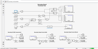
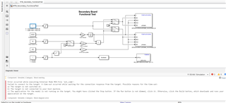
We are using this devices to monitoring a board designed to control another two high power boards via Simulink and serial communication. The issue is that the new debugger are not able to connect to the board that is using a F280048 microcontroller, while the previous debugger it is capable to connect.

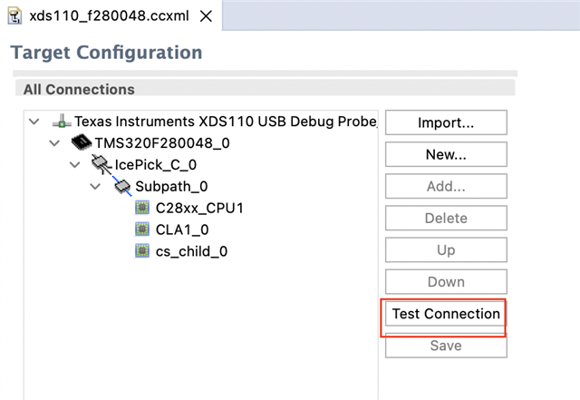
As you can see in this picture, with the first debuuger is running without issues and I able to control it.

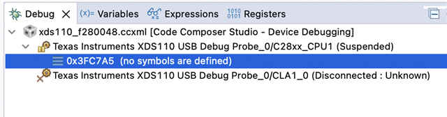
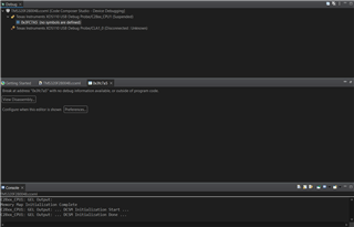
But with any of the new debuggers I am getting this error. And I am not changing anything (cables, program to load, setting on the serial ports, board to use) just changing the debugger.

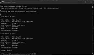
Also, all of them have the same firmware version.

I dont know that if there is some setting or change that I have to do to the new debugger to able to use them properly.


I hope you can help me.


Thank you.

  • Hi Alejandro,

    For debugging with Simulink, it is better to work with MathWorks team. We do not have resource to support Simulink debug issue.

    However, let's make sure your new XDS110 emulator works properly without Simulink. 

    Are you using TI EVM or you have custom board? Can you run any C2000Ware example and check if you are able to connect?

    Regards, Santosh

  • Hello.

    Thank you for your support. 

    Im not used to the TI products, do you have any guide that you can provide to try with an example from C2000Ware?

    And is not a TI EVM, it is a custom board with the uC F280048

  • Hi Alejandro,

    In CCS menu, View -> Target Configuration

    In the target configuration view, create a new target configuration.

    Select the debugger as XDS110, and your device, then press 'Save' button to save the target configuration.

    Now click 'Target Configuration', and then press 'Test Connection'.

    Can you send the message from Console window?

    Regards, Santosh

  • Hello. 

    I did the test as you suggested. This is the result that gave me

    [Start: Texas Instruments XDS110 USB Debug Probe]
    
    Execute the command:
    
    %ccs_base%/common/uscif/dbgjtag -f %boarddatafile% -rv -o -S integrity
    
    [Result]
    
    
    -----[Print the board config pathname(s)]------------------------------------
    
    C:\Users\uiv03662\AppData\Local\TEXASI~1\
        CCS\ccs1220\0\0\BrdDat\testBoard.dat
    
    -----[Print the reset-command software log-file]-----------------------------
    
    This utility has selected a 100/110/510 class product.
    This utility will load the adapter 'jioxds110.dll'.
    The library build date was 'Nov 28 2022'.
    The library build time was '16:30:46'.
    The library package version is '9.10.0.00080'.
    The library component version is '35.35.0.0'.
    The controller does not use a programmable FPGA.
    The controller has a version number of '5' (0x00000005).
    The controller has an insertion length of '0' (0x00000000).
    This utility will attempt to reset the controller.
    This utility has successfully reset the controller.
    
    -----[Print the reset-command hardware log-file]-----------------------------
    
    The scan-path will be reset by toggling the JTAG TRST signal.
    The controller is the XDS110 with USB interface.
    The link from controller to target is direct (without cable).
    The software is configured for XDS110 features.
    The controller cannot monitor the value on the EMU[0] pin.
    The controller cannot monitor the value on the EMU[1] pin.
    The controller cannot control the timing on output pins.
    The controller cannot control the timing on input pins.
    The scan-path link-delay has been set to exactly '0' (0x0000).
    
    -----[Perform the Integrity scan-test on the JTAG IR]------------------------
    
    This test will use blocks of 64 32-bit words.
    This test will be applied just once.
    
    Do a test using 0xFFFFFFFF.
    Scan tests: 1, skipped: 0, failed: 0
    Do a test using 0x00000000.
    Scan tests: 2, skipped: 0, failed: 0
    Do a test using 0xFE03E0E2.
    Scan tests: 3, skipped: 0, failed: 0
    Do a test using 0x01FC1F1D.
    Scan tests: 4, skipped: 0, failed: 0
    Do a test using 0x5533CCAA.
    Scan tests: 5, skipped: 0, failed: 0
    Do a test using 0xAACC3355.
    Scan tests: 6, skipped: 0, failed: 0
    All of the values were scanned correctly.
    
    The JTAG IR Integrity scan-test has succeeded.
    
    -----[Perform the Integrity scan-test on the JTAG DR]------------------------
    
    This test will use blocks of 64 32-bit words.
    This test will be applied just once.
    
    Do a test using 0xFFFFFFFF.
    Scan tests: 1, skipped: 0, failed: 0
    Do a test using 0x00000000.
    Scan tests: 2, skipped: 0, failed: 0
    Do a test using 0xFE03E0E2.
    Scan tests: 3, skipped: 0, failed: 0
    Do a test using 0x01FC1F1D.
    Scan tests: 4, skipped: 0, failed: 0
    Do a test using 0x5533CCAA.
    Scan tests: 5, skipped: 0, failed: 0
    Do a test using 0xAACC3355.
    Scan tests: 6, skipped: 0, failed: 0
    All of the values were scanned correctly.
    
    The JTAG DR Integrity scan-test has succeeded.
    
    [End: Texas Instruments XDS110 USB Debug Probe]
    

    But I don't see any console where I can send messages.

  • Hi,

    Looks like the emulator is fine. The test is running successfully.

    One more test we should try. Launch the target configuration. In the Target Configuration, select the one you created, right-click, and press 'Launch the  Selected Configuration"

    Once it is launched, select C28x in debug window, and then right-click, and select "Connect"

    Let me know if you are able to connect.

    Regards, Santosh

  • Hello.

    I think that that the expected result from you test.

    Right?

  • Hi,

    Yes, That is correct. Your board is fine and XDS110 emulator is fine.  For debugging Simulink, you will need to post to MathWorks forum. 

    Please take a look at MathWorks FAQ at this link below:


    If you have further questions, the best way to get support on MathWorks products is to contact MathWorks live tech support.

    You can also search for answers or post a question on MATLAB Answers C2000 forum. Additionally, there is info on MathWorks support C2000 in Documentation and Examples.


    I will close the thread from here as the software is supported by MathWorks team on their forum.

    Regards, Santosh

  • But my concerns with this test, is that were made with jtag, right?

    But thats not the issue, because with Simulink Im still able to download the program to the microcontroller and see the changes via osciloscope connected to a EPWM output.

    The problem start the Im trying to use UART interface to control it.

  • We tested the JTAG, and it seems to work fine. For UART, the Simulink probably is not setting correct COM port. Please create a post to MathWorks forum.

    We are not familiar with Simulink setup.

    Regards, Santosh

  • It is set correctly since one of he debugger works fine with the same setting 

  • Actually, we are not familiar with Simulink software. MathWorks team can support better, so I recommend you to post the question there. Your emulator is working fine. There is no issue in XDS110 emulator.

    You want to try SCI example from C2000Ware SDK, please try this this example:

    C:/ti/c2000/C2000Ware_4_01_00_00/driverlib/f28004x/examples/sci/sci_ex4_echoback.c

    Regards, Santosh