Part Number: TM4C1292NCPDT
Other Parts Discussed in Thread: TCA6416, TCA9555
Hi,
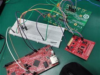
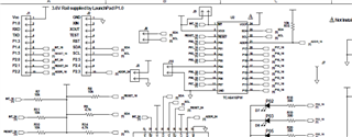
In my schematic, I'm connecting TM4C1292NCPDT to the IO expander IC TCA9555PWR through the I2C clock and data lines, SCL, and SDA.
I'm trying to run the following code with all 3 address lines as HIGH which means address is 0x27:
#include <stdarg.h>
#include <stdbool.h>
#include <stdint.h>
#include "inc/hw_i2c.h"
#include "inc/hw_memmap.h"
#include "inc/hw_types.h"
#include "inc/hw_gpio.h"
#include "driverlib/i2c.h"
#include "driverlib/sysctl.h"
#include "driverlib/gpio.h"
#include "driverlib/pin_map.h"
#include "xdc/std.h"
#include <ti/drivers/I2C.h>
uint32_t g_ui32SysClock;
bool bDiInitialized = FALSE;
#define DI_SLAVEADDRESS 0x27
//initialize I2C module 0
void InitI2C0(void)
{
//enable I2C module 0
SysCtlPeripheralEnable(SYSCTL_PERIPH_I2C0);
//reset module
SysCtlPeripheralReset(SYSCTL_PERIPH_I2C0);
//enable GPIO peripheral that contains I2C 0
SysCtlPeripheralEnable(SYSCTL_PERIPH_GPIOB);
// Configure the pin muxing for I2C0 functions on port B2 and B3.
GPIOPinConfigure(GPIO_PB2_I2C0SCL);
GPIOPinConfigure(GPIO_PB3_I2C0SDA);
// Select the I2C function for these pins.
GPIOPinTypeI2CSCL(GPIO_PORTB_BASE, GPIO_PIN_2);
GPIOPinTypeI2C(GPIO_PORTB_BASE, GPIO_PIN_3);
// Enable and initialize the I2C0 master module. Use the system clock for the I2C0 module. The last parameter sets the I2C data transfer rate.
// If false the data rate is set to 100kbps and if true the data rate will be set to 400kbps.
//I2CMasterInitExpClk(I2C0_BASE, SysCtlClockGet(), true);//for 400kbps tm4c123
I2CMasterInitExpClk(I2C0_BASE, SysCtlClockFreqSet((SYSCTL_XTAL_25MHZ | SYSCTL_OSC_MAIN | SYSCTL_USE_PLL | SYSCTL_CFG_VCO_480),120000000), true);//for 400kbps tm4c129
//clear I2C FIFOs
//HWREG(I2C0_BASE + I2C_O_FIFOCTL) = 80008000;
}
//I2C Send Function
//sends an I2C command to the specified slave
void I2CSend(uint8_t slave_addr, uint8_t num_of_args, ...)
{
uint8_t i ;
// Tell the master module what address it will place on the bus when
// communicating with the slave.
I2CMasterSlaveAddrSet(I2C0_BASE, slave_addr, false);
//stores list of variable number of arguments
va_list vargs;
//specifies the va_list to "open" and the last fixed argument so vargs knows where to start looking
va_start(vargs, num_of_args);
//put data to be sent into FIFO
I2CMasterDataPut(I2C0_BASE, va_arg(vargs, uint32_t));
//if there is only one argument, we only need to use the single send I2C function
if(num_of_args == 1)
{
//Initiate send of data from the MCU
I2CMasterControl(I2C0_BASE, I2C_MASTER_CMD_SINGLE_SEND);
// Wait until MCU is done transferring.
while(!(I2CMasterBusy(I2C0_BASE)));
while(I2CMasterBusy(I2C0_BASE));
//"close" variable argument list
va_end(vargs);
}
//otherwise, we start transmission of multiple bytes on the I2C bus
else
{
//Initiate send of data from the MCU
I2CMasterControl(I2C0_BASE, I2C_MASTER_CMD_BURST_SEND_START);
// Wait until MCU is done transferring.
while(!(I2CMasterBusy(I2C0_BASE)));
while(I2CMasterBusy(I2C0_BASE));
//send num_of_args-2 pieces of data, using the
//BURST_SEND_CONT command of the I2C module
for( i = 1; i < (num_of_args - 1); i++)
{ //put next piece of data into I2C FIFO
I2CMasterDataPut(I2C0_BASE, va_arg(vargs, uint32_t));
//send next data that was just placed into FIFO
I2CMasterControl(I2C0_BASE, I2C_MASTER_CMD_BURST_SEND_CONT);
// Wait until MCU is done transferring.
while(!(I2CMasterBusy(I2C0_BASE)));
while(I2CMasterBusy(I2C0_BASE));
}
//put last piece of data into I2C FIFO
I2CMasterDataPut(I2C0_BASE, va_arg(vargs, uint32_t));
//send next data that was just placed into FIFO
I2CMasterControl(I2C0_BASE, I2C_MASTER_CMD_BURST_SEND_FINISH);
// Wait until MCU is done transferring.
while(!(I2CMasterBusy(I2C0_BASE)));
while(I2CMasterBusy(I2C0_BASE));
//"close" variable args list
va_end(vargs);
} }
//sends an array of data via I2C to the specified slave
void I2CSendString(uint32_t slave_addr, char array[])
{ // Tell the master module what address it will place on the bus when communicating with the slave.
I2CMasterSlaveAddrSet(I2C0_BASE, slave_addr, false);
//put data to be sent into FIFO
I2CMasterDataPut(I2C0_BASE, array[0]);
//if there is only one argument, we only need to use the
//single send I2C function
if(array[1] == '\0')
{
//Initiate send of data from the MCU
I2CMasterControl(I2C0_BASE, I2C_MASTER_CMD_SINGLE_SEND);
// Wait until MCU is done transferring.
while(!(I2CMasterBusy(I2C0_BASE)));
while(I2CMasterBusy(I2C0_BASE));
}
//otherwise, we start transmission of multiple bytes on the I2C bus
else
{ //Initiate send of data from the MCU
I2CMasterControl(I2C0_BASE, I2C_MASTER_CMD_BURST_SEND_START);
// Wait until MCU is done transferring.
while(!(I2CMasterBusy(I2C0_BASE)));
while(I2CMasterBusy(I2C0_BASE));
//initialize index into array
uint8_t i = 1;
//send num_of_args-2 pieces of data, using the
//BURST_SEND_CONT command of the I2C module
while(array[i + 1] != '\0')
{ //put next piece of data into I2C FIFO
I2CMasterDataPut(I2C0_BASE, array[i++]);
//send next data that was just placed into FIFO
I2CMasterControl(I2C0_BASE, I2C_MASTER_CMD_BURST_SEND_CONT);
// Wait until MCU is done transferring.
while(!(I2CMasterBusy(I2C0_BASE)));
while(I2CMasterBusy(I2C0_BASE));
}
//put last piece of data into I2C FIFO
I2CMasterDataPut(I2C0_BASE, array[i]);
//send next data that was just placed into FIFO
I2CMasterControl(I2C0_BASE, I2C_MASTER_CMD_BURST_SEND_FINISH);
// Wait until MCU is done transferring.
while(!(I2CMasterBusy(I2C0_BASE)));
while(I2CMasterBusy(I2C0_BASE));
} }
//I2C Receive Function
//read specified register on slave device
uint32_t I2CReceive(uint32_t slave_addr, uint8_t reg)
{ //specify that we are writing (a register address) to the
//slave device
I2CMasterSlaveAddrSet(I2C0_BASE, slave_addr, false);
//specify register to be read
I2CMasterDataPut(I2C0_BASE, reg);
//send control byte and register address byte to slave device
I2CMasterControl(I2C0_BASE, I2C_MASTER_CMD_BURST_SEND_START);
//wait for MCU to finish transaction
while(I2CMasterBusy(I2C0_BASE));
//specify that we are going to read from slave device
I2CMasterSlaveAddrSet(I2C0_BASE, slave_addr, true);
//send control byte and read from the register we specified
I2CMasterControl(I2C0_BASE, I2C_MASTER_CMD_SINGLE_RECEIVE);
//wait for MCU to finish transaction
while(!(I2CMasterBusy(I2C0_BASE)));
while(I2CMasterBusy(I2C0_BASE));
//return data pulled from the specified register
return I2CMasterDataGet(I2C0_BASE);
} }
void main(void)
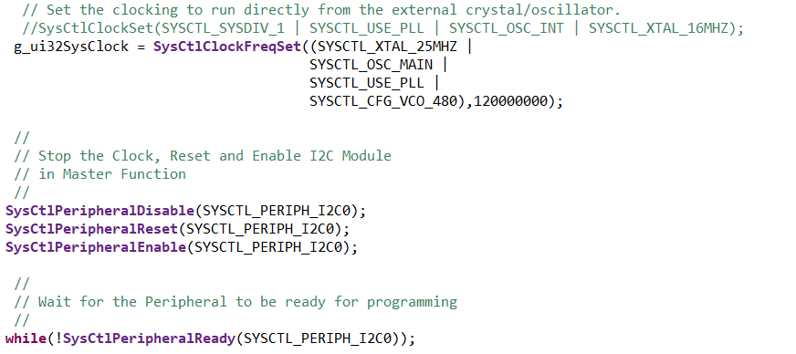
{ // Set the clocking to run directly from the external crystal/oscillator.
g_ui32SysClock = SysCtlClockFreqSet((SYSCTL_XTAL_25MHZ |
SYSCTL_OSC_MAIN |
SYSCTL_USE_PLL |
SYSCTL_CFG_VCO_480),120000000);
//initialize I2C module 0
InitI2C0();
I2CSend(DI_SLAVEADDRESS, 3, 0, 0, 0x01);
I2CSend(DI_SLAVEADDRESS, 3, 0x06, 0x01, 0);//configuration port 0
while(1){};
}
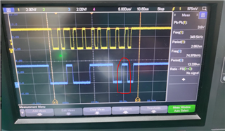
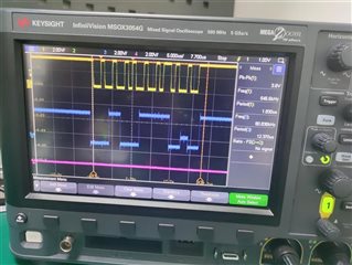
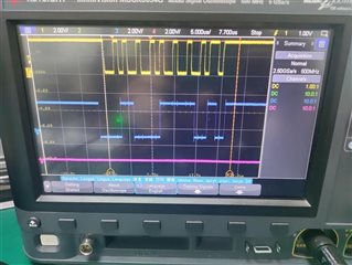
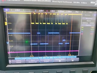
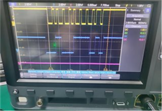
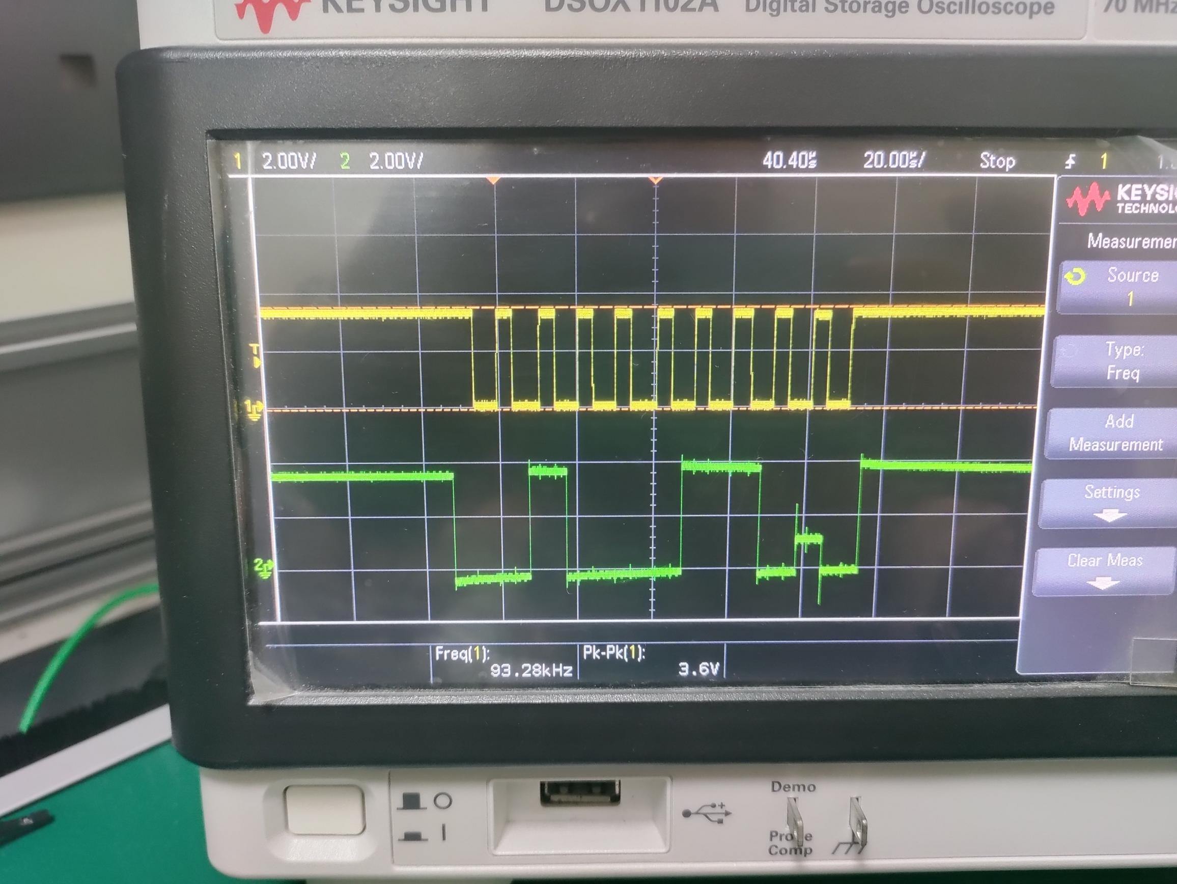
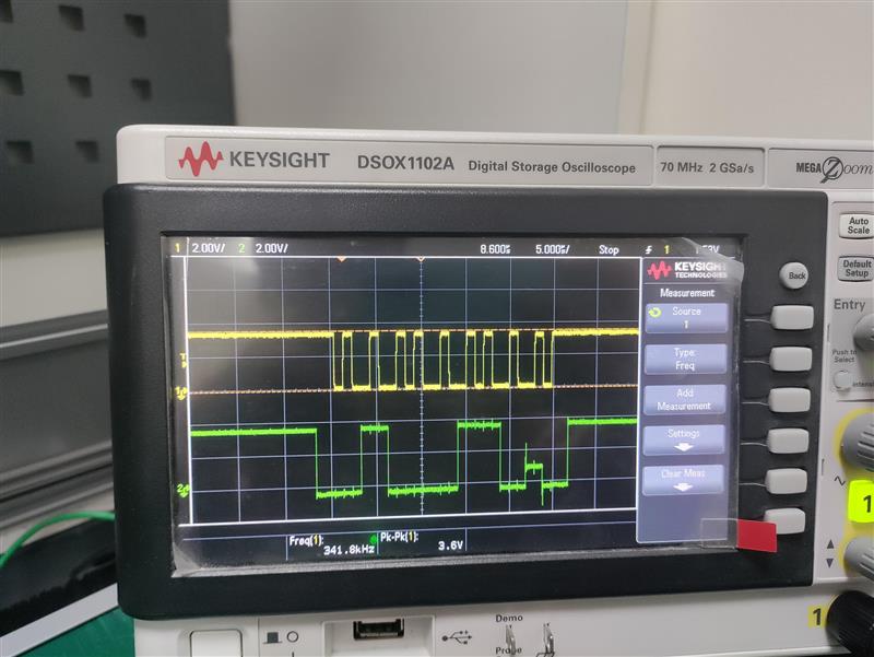
But from the scope capture, only single I2C send command seems to be working not multiple.
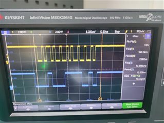
Please guide for the same.
Best Regards,
Kiranjit