This thread has been locked.
If you have a related question, please click the "Ask a related question" button in the top right corner. The newly created question will be automatically linked to this question.
Hello,
A similar question was posted a couple of years ago, but the solution comprised using the BSL Rocket. Can you please provide the steps to boot off the UART port without using a MSP Rocket?
Magda
Hi,
You don't need a MSP Rocket. If you have a LaunchPad then the on-board XDS110 debug probe has a back channel USB-to-UART bridge that can communicate with your UART on the target device. If you are not using the LaunchPad, then you will need a USB-to-UART bridge such as FTDI IC.
Please refer to section 4 of the user's guide for details.
https://www.ti.com/lit/slau655
Flash-based serial bootloader example can be found at:
C:\ti\simplelink_msp432e4_sdk_4_20_00_12\examples\nortos\MSP_EXP432E401Y\boot_loader\boot_serial_uart_flash
BSL scripter command line scripts example for UART can be found at:
C:\ti\BSL-Scripter\ScriptExampleWindows\E4xx_uart
Can you explain why you rejected my answer without giving a reason? I thought I explained you that without MSP Rocket, you would need an USB-to-UART converter that will enumerate as a virtual COM port so the PC host can communicate with MCU through UART. Modern PCs do not have a UART port anymore and this is the reason for the converter. If you use the LaunchPad, the onboard XDS110 debug probe has the USB to UART converter built in. What was not answered in my last reply?
Hello Charles,
I absolutely did not reject your answer, on the contrary thank you for your prompt reply. You answered everything. Can it be I mistakenly pressed the wrong button? Apologies if it happened. I am looking at both UART and USB approaches. My experiments will inform our HW design, and I am a bit pressed in time.
Thank you again,
Magda
What if I have additional questions? Shall I open a new ticket? I'm going to look at the UART now.
Regards,
Magda
Hi,
If you have new questions that are not related to UART bootloader then please open a new post. If the questions are related to UART bootloader you can just write back to this thread and the thread will automatically reopen. I will be notified.
Hello Charles,
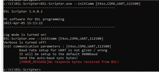
I successfully ran the scripts: script_1 through script_3 in ti\BSL-Scripter\ScriptExampleWindows\E4xx_uart. To erase the flash I used the CCS gel file MSP432E4_MASS_ERASE. I did not populate R5 and R6 with 0-ohm resistor since I am not using the BSL-Rocket. Next, I tried to use the CLI commands to reproduce the steps in script_1 through script_3. The first step I tried was to initialize communication channel as below:
What am I missing?
Also I'd like to erase the flash using the CLI command --erase [MASS_ERASE]. I assume --initComm is a prerequisite to it.
Regards, Magda
Hi,
Please refer to this post for details that uses command line to mass-erase MSP432E. https://e2e.ti.com/support/microcontrollers/msp-low-power-microcontrollers-group/msp430/f/msp-low-power-microcontroller-forum/655218/msp432e411y-does-a-tool-exist-to-recover-locked-msp432
The command to use will be as follows.
dbgjtag.exe -f @xds110 -Y unlock,mode=msp432e4
Thank you Charles. It worked only once. In other words I called:
1. dbgjtag.exe -f @xds110 -Y unlock, mode=msp432e4
power down/up
2. BSL_Scripter.exe --erase ERASE_ALL
power down/up
and then I called script1 and script2.
I see the blinking.
When I repeat steps 1 and 2 I still see the LED1 light blinking, so the steps did not erase the flash.
My goal is to swap between two applications by just using steps similar to script_1 through script_3. On our final hardware, I will not have access to a JTAG and a button like SW1, so to run app1 and then swap to app2:
1. erase flash;
2. load custom uart bootloader in flash (script_1);
3. load app1.
To load app2 repeat 1. and 2 and then load app2.
Regards,
Magda
Hi,
What type of board do you have and what debug probe do you use? The dbgjtag.exe @xds110 is for the XDS110 debug probe. The LaunchPad has the onboard XDS110 debug probe. If you have a different debug probe (e.g. XDS200) on a custom board then you need to change it accordingly on the command line. dbgjtag.exe is supposed to mass-erase the chip completely including all non-volatile registers and EEprom. There is no need to do BSL_Scripter.exe --erase ERASE_ALL. After you run dbgjtag command, does it return any error message? If you use CCS memory browser, do you see the flash become 0xFFFFFFFF on any memory addresses?
Hi Charles,
Thank you for your reply. I realize now that there will not be an onboard XDS110 or XDS200 debug probe. So simply swapping between two apps via the BSL-Scripter will not work. I'm looking for additional ways, so far without success. Page 5 of MSP432E4 SimpleLink Microcontrollers Bootloader (BSL) User's Guide (Rev. A) (ti.com) explains ways to initiate an application update by checking for a valid stack pointer and reset handler or using a GPIO. But those have to be triggered externally and this implies either using a button connected to the GPIO (looks it won't be available) or modifying the BSL_Scripter app (would like to avoid). What would be the simplest solution?
Regards,
Magda
Hi,
You need to come up with a method for the application to jump back to the bootloader. This can be done by toggling a GPIO or you can send a message to the application. Upon receiving the message, the application can then jump to the bootloader. That message can be sent through any serial port you want, be it SPI or UART or others. Of course the corresponding serial port that you want to receive that message must be setup in the application first.
Thank you Charles for your reply. I have questions pertaining to the interaction between the bootloader, the MSP432E4xx app and the PC based app:
1. Do I fold the bootloader code into my app? Otherwise, how does my app invoke ConfigureDevice() and Updater()?
2. If the update is triggered by a GPIO, I need to set up the GPIO Interrupt handler to invoke Updater(), assuming the serial port was already configured. Can you point me to a similar piece of code?
3. On the PC side: does the BSL-Scripter, as is, support a new application download for either a GPIO or an application triggered update? Obviously it should conform to what's described in Sections 3.3-3.6 of https://www.ti.com/lit/ug/slau746a/slau746a.pdf and I see some indication it is. Does it need to be modified? Does TI provide anything else i could easily modify? Again I'm NOT using a BSL Rocket.
Regards,
Magda
Hi,
1. Do I fold the bootloader code into my app? Otherwise, how does my app invoke ConfigureDevice() and Updater()?
Please refer to the example application that jumps back to the bootloader when a GPIO pin is asserted. As you can see, this example application will setup the UART, I2C and SPI ports. Upon detecting a GPIO assertion (e.g. pressing the SW1 on the LaunchPad), it will call JumpToLoader() that jumps to the bootloader. You do not need to call ConfigureDevice inside the application. ConfigureDevice is a function that bootloader calls when the bootloader is running. The bootloader will call Updater() to start the firmware update. This is all handled by the bootloader. Your application just needs to have a mechanism to jump back to the bootloader. The rest is taken care by bootloader itself.
C:\ti\simplelink_msp432e4_sdk_4_20_00_12\examples\nortos\MSP_EXP432E401Y\boot_loader\boot_serial_flash_app2
3. On the PC side: does the BSL-Scripter, as is, support a new application download for either a GPIO or an application triggered update? Obviously it should conform to what's described in Sections 3.3-3.6 of https://www.ti.com/lit/ug/slau746a/slau746a.pdf and I see some indication it is. Does it need to be modified? Does TI provide anything else i could easily modify? Again I'm NOT using a BSL Rocket.
The BSL-scripter does not know if the MCU client is application mode or bootloader mode. In another word, it does not know when the application has jumped back to the bootloader. You will need to handle that. I wouldn't suggest you modify BSL-Scripter. Rather, I would suggest you develop a separate but simple PC application that sends a UART message to the application. When the application receives this unique message then it will jump to the bootloader. You could combine this simple PC application and BSL-Scripter in a batch file if that makes it easier for you.
Thanks Charles for your clarifications and pointers. I was studying the example boot_serial_uart_flash in the same directory and could not find immediate answers to my questions 1 and 2.
This example, brings me to a different question. The HW person would like to use UART1 instead of UART0. So based on this example I should configure for UART1 in SetupForUART(). Anything else?
Regards,
Magda
I was studying the example boot_serial_uart_flash in the same directory and could not find immediate answers to my questions 1 and 2.
boot_serial_uart_flash is the flash-based bootloader while boot_serial_flash_app2 is the application.
This example, brings me to a different question. The HW person would like to use UART1 instead of UART0. So based on this example I should configure for UART1 in SetupForUART(). Anything else?
You can use bl_config.h in the boot_serial_uart_flash example to configure for a different UART, such as UART1. Below is the snippet of #define that needs to change for whichever UARTx you want to use. By default it is UART0.
//***************************************************************************** // // Selects the baud rate to be used for the UART. // // Depends on: UART_ENABLE_UPDATE, CRYSTAL_FREQ // Exclusive of: UART_AUTOBAUD // Requires: None // //***************************************************************************** #define UART_FIXED_BAUDRATE 115200 //***************************************************************************** // // Selects the clock enable for the UART peripheral module // // Depends on: UART_ENABLE_UPDATE // Exclusive of: None // Requires: UARTx // //***************************************************************************** #define UART_CLOCK_ENABLE SYSCTL_RCGCUART_R0 //***************************************************************************** // // Selects the base address of the UART peripheral module // // Depends on: UART_ENABLE_UPDATE // Exclusive of: None // Requires: UART_CLOCK_ENABLE // //***************************************************************************** #define UARTx UART0 //***************************************************************************** // // Selects the clock enable for the GPIO corresponding to UART RX pin // // Depends on: UART_ENABLE_UPDATE // Exclusive of: None // Requires: UART_RXPIN_BASE, UART_RXPIN_PCTL and UART_RXPIN_POS // //***************************************************************************** #define UART_RXPIN_CLOCK_ENABLE SYSCTL_RCGCGPIO_R0 //***************************************************************************** // // Selects the base address for the GPIO corresponding to UART RX pin // // Depends on: UART_ENABLE_UPDATE // Exclusive of: None // Requires: UART_RXPIN_CLOCK_ENABLE, UART_RXPIN_PCTL and UART_RXPIN_POS // //***************************************************************************** #define UART_RXPIN_BASE GPIOA //***************************************************************************** // // Selects the port control value for the GPIO corresponding to UART RX pin // // Depends on: UART_ENABLE_UPDATE // Exclusive of: None // Requires: UART_RXPIN_CLOCK_ENABLE, UART_RXPIN_BASE and UART_RXPIN_POS // //***************************************************************************** #define UART_RXPIN_PCTL 0x1 //***************************************************************************** // // Selects the pin number for the GPIO corresponding to UART RX pin // // Depends on: UART_ENABLE_UPDATE // Exclusive of: None // Requires: UART_RXPIN_CLOCK_ENABLE, UART_RXPIN_BASE and UART_RXPIN_PCTL // //***************************************************************************** #define UART_RXPIN_POS 0 //***************************************************************************** // // Selects the clock enable for the GPIO corresponding to UART TX pin // // Depends on: UART_ENABLE_UPDATE // Exclusive of: None // Requires: UART_TXPIN_BASE, UART_TXPIN_PCTL and UART_TXPIN_POS // //***************************************************************************** #define UART_TXPIN_CLOCK_ENABLE SYSCTL_RCGCGPIO_R0 //***************************************************************************** // // Selects the base address for the GPIO corresponding to UART TX pin // // Depends on: UART_ENABLE_UPDATE // Exclusive of: None // Requires: UART_TXPIN_CLOCK_ENABLE, UART_TXPIN_PCTL and UART_TXPIN_POS // //***************************************************************************** #define UART_TXPIN_BASE GPIOA //***************************************************************************** // // Selects the port control value for the GPIO corresponding to UART TX pin // // Depends on: UART_ENABLE_UPDATE // Exclusive of: None // Requires: UART_TXPIN_CLOCK_ENABLE, UART_TXPIN_BASE and UART_TXPIN_POS // //***************************************************************************** #define UART_TXPIN_PCTL 0x1 //***************************************************************************** // // Selects the pin number for the GPIO corresponding to UART TX pin // // Depends on: UART_ENABLE_UPDATE // Exclusive of: None // Requires: UART_TXPIN_CLOCK_ENABLE, UART_TXPIN_BASE and UART_TXPIN_PCTL // //***************************************************************************** #define UART_TXPIN_POS 1
Sorry Charles, but I'm missing something. Assume I generated a new binary boot_serial_uart_flash configured for UART1. This is easy. How does it get to the right location in flash?
Also does one need to start with an empty flash?
Sorry Charles, but I'm missing something. Assume I generated a new binary boot_serial_uart_flash configured for UART1. This is easy. How does it get to the right location in flash?
This is why you run script_1.txt. When the flash is empty, the ROM-based bootloader will load the flash-based bootloader boot_serial_uart_flash to flash through the UART port. You can easily program boot_serial_uart_flash using JTAG if you want but my understanding is that you will not have JTAG access on your final production board. Therefore, you will use the ROM-based bootloader. Think of ROM-based bootloader as a one time thing. Once you have something in the flash, the ROM-based bootloader will just jump to 0x0 to run whatever program you have there, be it a flash-based bootloader or a an application.
Also does one need to start with an empty flash?
As explained above, for the very first time to use the ROM bootloader to load your flash-based bootloader, the flash must be empty first.
One clarification I must make is that ROM-based bootloader will only work for UART0 and not other UART ports. Therefore, you will load your flash-based bootloader through UART0 port and once the flash-based bootloader is running, it will use UART1 port to load your final firmware. As I said before, you can also use JTAG to load your flash based bootloader just like loading any application such as blinky or hello using CCS or Uniflash.
Charles you just sent another reply but it disappeared. I only saw you were mentioning UART0 first time and then switching to UART1. My issue: I have access to one UART, it can be either UART0 or UART1.
I guess it's fine to program the bootloader with the JTAG and load my firmware and subsequent firmware versions via UART1.
Hi Charles,
I tried to JTAG flash the UART based bootloader (still using UART0) just to verify the sequence of steps Compiled and loaded using JTAG in CCS. Before loading, I erased the flash with MASS_ERASE script provided by CCS. Next I closed CCS, reset and ran script_2 since if everything went OK, the booltoader is in flash. No luck.
What could be the issue?
Best,
Magda
Hi,
I erased the flash with MASS_ERASE script provided by CCS.
You don't really need to do a mass_erase since you are using JTAG to download the code. A erase is only needed if you are to use the ROM-base bootloader to load your program through a serial interface. If you are going to use JTAG to download the code in CCS, you just download it like any programs such blinky or hello.
Also there is a difference between erase and mass-erase. A mass-erase will erase not only the flash but also all non-volatile registers and EEprom. If you are going to use the ROM bootloader to download code through UART or any serial interface, you just need to do a regular erase is enough. But if you find it more convenient to do mass_erase, it is ok too.
Next I closed CCS, reset and ran script_2 since if everything went OK, the booltoader is in flash. No luck.
- Check your flash bootloader image that you try to load using JTAG. Is it the C:\ti\BSL-Scripter\ScriptExampleWindows\E4xx_uart\boot_uart_flash_MSP-EXP432E401Y.txt?
- Next check the content of the flash in CCS memory browser. Do you see the flash bootloader image starting at 0x0?
- Next, Can you reset the device before running script_2.txt?
- Next check the COM port in script_2.txt. Do you have the correct COM port that is shown in device manager?
- I have no issue running the above steps
Heads-up, today is a US holiday for my company. I'm on vacation until Monday afternoon. Please expect delay in my response.
Have a good long weekend Charles and thank you very much for all your help. Will be in touch Monday.
I was doing all the steps you recommended except "erase". No luck. Further, it occurs to me that each time I will need to swap apps, UART! bootloader needs to be in flash at address 0x0. This means either downloading and writing it to flash via UART0, or using the JTAG to flash. In production mode there is not going to be access to the JTAG connector and only to one UART port will be available pre-selected as either 0 or 1. So I guess in my circumstances using UART1 won't work. I'll look into it some more.
Best,
Magda
Correction: I realize that the UARt1-based bootloader can be flashed ONCE at memory address 0x0 and be resident there, since the apps start at 0x4000. So this should work.
Best,
Magda
Hi Charles,
Here is my status:
1. Getting error message "No response bytes received from BSL" when:
a. I compile and build the project boot_serial_uart_flash_MSP_EXP432E401Y_nortos_ccs,
b. JTAG program the file boot_serial_uart_flash_MSP_EXP432E401Y_nortos_ccs.out in flash,
c. close CCS, reset LaunchPad
d. run script_2.txt
2. Success when:
a. I erase flash,
b. reset LaunchPad
c. run script_1
d. reset LaunchPad
e. run script_2
Clearly the ROM bootloader does some extra steps when it downloads and writes boot_serial_uart_flash_MSP_EXP432E401Y.txt to flash. Also are the 2 files the same just different in format - out vs. txt?
Magda
Hi Magda,
Let's make sure you can successfully use JTAG to load the C:\ti\BSL-Scripter\ScriptExampleWindows\E4xx_uart\boot_uart_flash_MSP-EXP432E401Y.txt instead of the .out file that you build because I don't know what you changed to the bl_config.h. Please do as follows:
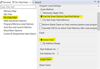
1. Erase the flash. In CCS, you can erase as follows. Go to Tools->On-Chip Flash and hit 'Erase Flash' button. Go to memory window and look at address at 0x0 and the rest become all 0xFFFFFFFF.
2. In CCS, go to Run->Load-> Load Program to use JTAG to load C:\ti\BSL-Scripter\ScriptExampleWindows\E4xx_uart\boot_uart_flash_MSP-EXP432E401Y.txt. You can use Uniflash too. Go to memory window and confirm the flash bootloader is programmed to 0x0.
3. Reset the LaunchPad.
4. Run script_2.txt. Make sure you have the correct COM port in the script.
The above are the steps I use and it works for me.
Hi Charles,
Many thanks! Your steps worked. I also reimported the project boot_serial_uart_flash_MSP_EXP432E401Y_nortos_ccs rebuilt it and repeated your steps. It worked too. Not sure how I broke the initial import - double-checked I reverted that single #define back to UART0.
I actually can use UART0.
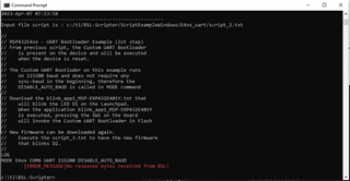
Finally I have another question: while running blink_app2_MSP-EXP432E401Y, and after pressing the SW1 button, I tried to call a script erasing a 16kB of flash: as below:
LOG
MODE E4xx COM6 UART 115200 DISABLE_AUTO_BAUD
DEBUG
ERASE_SEGMENT_32 0x8000
I have the bootloader at address 0x0 and the blink_app2_MSP-EXP432E401Y at APP_BASE==0x400. No success.
Without the DISABLE_AUTO_BAUD attribute, the BSL is not acknowledging the command and the error message displayed is "No response bytes received from BSL".
Thank you again,
Magda
Hi Magda,
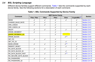
Please refer to the BSL-scripter user's guide for details. ERASE_SEGMENT_32 and quite a few other commands are not supported for MSP432E device.
Thanks again Charles!
Indeed I misread the spec, trying a few things. I now notice that if UART communication is selected, erasing memory is not supported. for the MSP432E. And one (hopefully) final question: Section 3.1.11 mentions main memory. Is this flash memory only or this comprises also the EEPROM, and volatile registers?
Best.
Magda
Hi Charles,
Suppose I use the JTAG or Uniflash to flash the UART0 bootloader and an initial version of the FW. When an update is needed, a command is sent to the resident FW app to update. As a result, the FW app jumps to the bootloader. Next, I run script_2, modified with the name of my new FW file. What happens if mid-way during the file download the cable, who also supplies power, is yanked? The flash has a partially downloaded application. Is there a way to recover without the JTAG?
As a side note, based on the Bootloader (BSL) Scripter documentation, I cannot run a script to erase the MSP432Exx flash unless the bootloader is configured for USB.
Best,
Magda
Hi Magda,
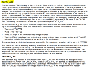
You can implement CRC check. If the firmware update is not complete then the bootloader will wait for the new image again.