Part Number: TM4C1292NCPDT
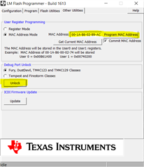
Other Parts Discussed in Thread: UNIFLASH
Hi,
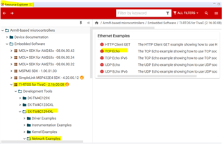
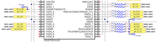
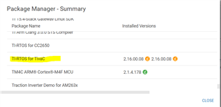
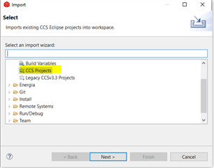
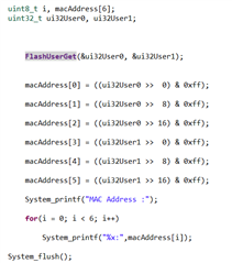
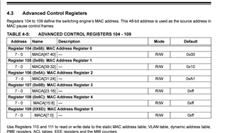
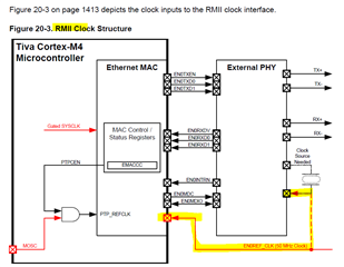
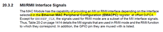
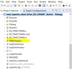
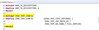
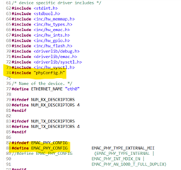
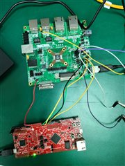
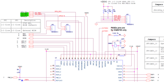
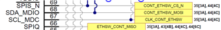
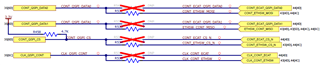
I am using TM4C1292NCPDT in our custom board to validate interface between external PHY(KSZ8765) and controller. I used the code from thread (RTOS/TM4C1292NCPDT: Issue in External PHY configuration through MII interface - Arm-based microcontrollers forum - Arm-based microcontrollers - TI E2E support forums ) and modified as per my application.
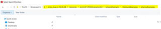
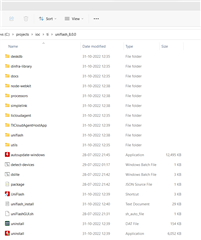
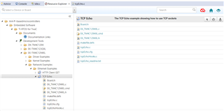
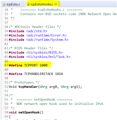
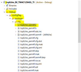
Modified code has been attached./cfs-file/__key/communityserver-discussions-components-files/908/tcpEcho_5F00_B.zip
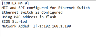
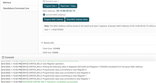
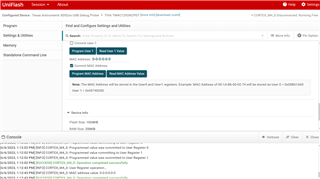
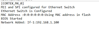
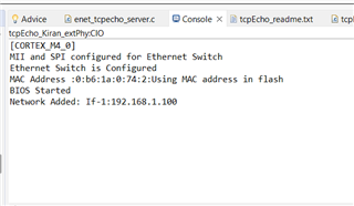
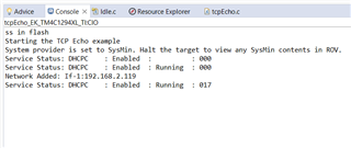
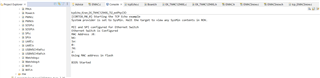
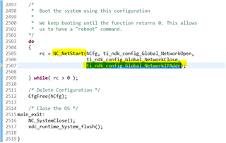
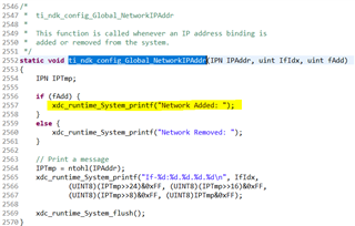
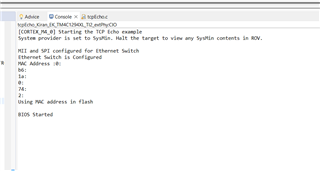
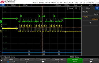
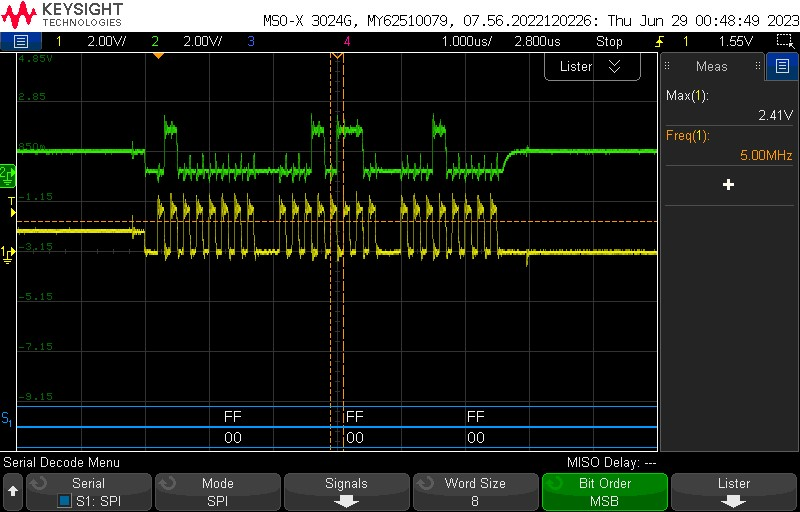
I am able to configure the switch.
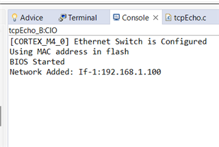
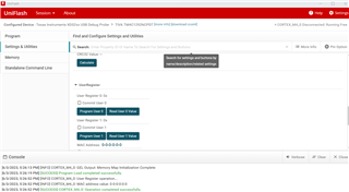
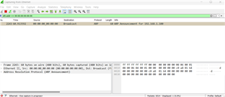
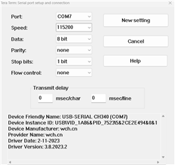
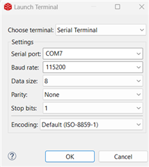
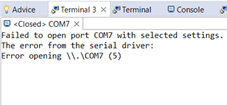
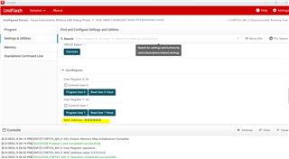
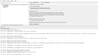
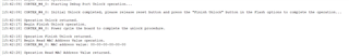
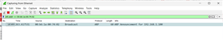
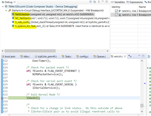
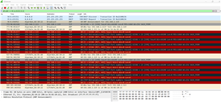
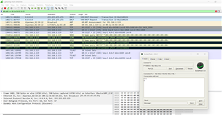
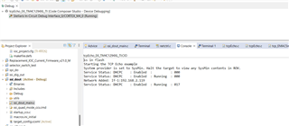
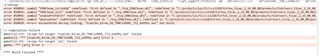
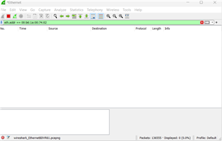
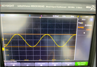
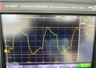
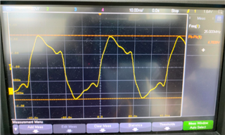
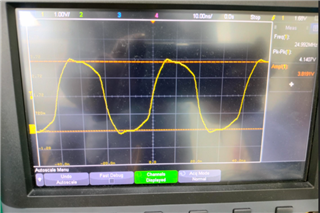
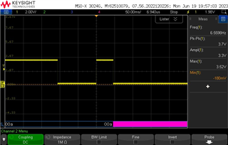
But not able to get output on Wireshark and Terminal window. See below
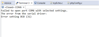
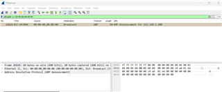
Please share your feedback or suggestions.
Thanks,
Kiran