This thread has been locked.

If you have a related question, please click the "Ask a related question" button in the top right corner. The newly created question will be automatically linked to this question.

TM4C129EKCPDT: I2C ACK/NACK issue

Genius 16680 points
Part Number: TM4C129EKCPDT
Other Parts Discussed in Thread: TMP1075

Hi Experts,

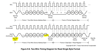
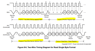
We are facing some issue with I2C ACK/NACK we are sending 3 byte in i2c line but it is sending only two byte:

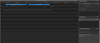
second byte missing.

Fullscreen
1
2
3
4
5
6
7
8
9
10
11
12
13
14
15
16
17
18
19
20
21
MAP_I2CMasterDataPut(I2C2_BASE, 0x00); //0x10
MAP_I2CMasterControl(I2C2_BASE, I2C_MASTER_CMD_BURST_SEND_START);
while(MAP_I2CMasterBusy(I2C2_BASE));
// while(!(MAP_I2CSlaveStatus(I2C2_BASE) & I2C_SLAVE_ACT_RREQ_FBR))
{
}
MAP_I2CMasterDataPut(I2C2_BASE, Dpot_Resistance_Todecimal); // value N
MAP_I2CMasterControl(I2C2_BASE, I2C_MASTER_CMD_BURST_SEND_FINISH); //I2C_MASTER_CMD_BURST_SEND_CONT
while(MAP_I2CMasterBusy(I2C2_BASE));
void init_i2c_init(void)
{
MAP_SysCtlPeripheralDisable(SYSCTL_PERIPH_I2C2);
MAP_SysCtlPeripheralReset(SYSCTL_PERIPH_I2C2);
MAP_SysCtlPeripheralEnable(SYSCTL_PERIPH_I2C2);
MAP_SysCtlPeripheralEnable(SYSCTL_PERIPH_GPIOL); //system enable gpio port L
MAP_SysCtlPeripheralEnable(SYSCTL_PERIPH_I2C2); // I2C2 system enable
MAP_GPIOPinConfigure(GPIO_PL1_I2C2SCL); //I2C2 clk gpio config port PL1
MAP_GPIOPinConfigure(GPIO_PL0_I2C2SDA); //I2C2 data PORT PL0
MAP_GPIOPinTypeI2C(GPIO_PORTL_BASE, GPIO_PIN_0); // PL0 is data
XXXXXXXXXXXXXXXXXXXXXXXXXXXXXXXXXXXXXXXXXXXXXXXXXX

I2C bytes : 82 ,0,253
82(0x29) is the address of the slave device, It is not sending 0(Zero).
It is sending 82 and 253 only, Why?
Am i doing some mistake?

***

Thank you.

Regards,
Archie A.

  • Hi,

      Please change at every place you have the below line,

    FROM:

    while(MAP_I2CMasterBusy(I2C2_BASE));

    TO:

    while(!MAP_I2CMasterBusy(I2C2_BASE)) // Add this line  before everywhere you have while(MAP_I2CMasterBusy(I2C2_BASE)).

    while(MAP_I2CMasterBusy(I2C2_BASE));

  • Thank you, Charles.

    That problem solved by your help and suggestion.
    but now we have another problem for read the two bytes from i2c slave, we are not getting any data from slave.
    We are using TMP1075NDRLR for Ti, Please find the attached screen shot.
    //for reading
    {
    MAP_I2CMasterDataPut(I2C2_BASE, 0x00);
    MAP_I2CMasterControl(I2C2_BASE, I2C_MASTER_CMD_BURST_RECEIVE_START);
    while(!MAP_I2CMasterBusy(I2C2_BASE))
    {

    }
    while(MAP_I2CMasterBusy(I2C2_BASE));
    Board_temp =MAP_I2CMasterDataGet(I2C2_BASE);
    while(!MAP_I2CMasterBusy(I2C2_BASE))
    {

    }
    while(MAP_I2CMasterBusy(I2C2_BASE));
    Board_temp =MAP_I2CMasterDataGet(I2C2_BASE);
    while(!MAP_I2CMasterBusy(I2C2_BASE))
    {

    }
    while(MAP_I2CMasterBusy(I2C2_BASE));
    MAP_I2CMasterControl(I2C2_BASE, I2C_MASTER_CMD_BURST_RECEIVE_FINISH);

    }

    Regards,
    Archie A.

  • Hi Archie,

     I'm not familiar with TMP1075NDRLR but does your I2C waveform for reads conform to what is shown in  TMP1075NDRLR  datasheet.

    In your code, I don't see you start with a slave address byte. Your first line starts with MAP_I2CMasterDataPut(I2C2_BASE, 0x00) which is writing data to the TX buffer. What is this for? Where are you starting a Slave Address byte for read like shown in the above timing diagram?

    Below is an example reading from a I2C device. 

    Fullscreen
    1
    2
    3
    4
    5
    6
    7
    8
    9
    10
    11
    12
    13
    14
    15
    16
    17
    18
    19
    20
    21
    void
    I2CReadCommand(uint32_t * pui32DataRx)
    {
    //
    // Modify the data direction to true, so that seeing the address will
    // indicate that the I2C Master is initiating a read from the slave.
    //
    MAP_I2CMasterSlaveAddrSet(I2C7_BASE, SHT21_I2C_ADDRESS, true);
    //
    // Setup for first read. Use I2C_MASTER_CMD_BURST_RECEIVE_START
    // to start a burst mode read. The I2C master continues to own
    // the bus at the end of this transaction.
    //
    MAP_I2CMasterControl(I2C7_BASE, I2C_MASTER_CMD_BURST_RECEIVE_START);
    //
    // Wait until master module is done transferring.
    // The I2C module has a delay in setting the Busy flag in the register so
    // there needs to be a delay before checking the Busy bit. The below loops
    // wait until the Busy flag is set, and then wait until it is cleared to
    XXXXXXXXXXXXXXXXXXXXXXXXXXXXXXXXXXXXXXXXXXXXXXXXXX

  • Thank you, Charles.

    For i2c init and salve address setup
    void temp_sensor(void)
    {
    MAP_SysCtlPeripheralDisable(SYSCTL_PERIPH_I2C2);
    MAP_SysCtlPeripheralReset(SYSCTL_PERIPH_I2C2);
    MAP_SysCtlPeripheralEnable(SYSCTL_PERIPH_I2C2);
    MAP_SysCtlPeripheralEnable(SYSCTL_PERIPH_GPIOL);
    MAP_SysCtlPeripheralEnable(SYSCTL_PERIPH_I2C2);
    MAP_GPIOPinConfigure(GPIO_PL1_I2C2SCL);
    MAP_GPIOPinConfigure(GPIO_PL0_I2C2SDA); //I2C2 data PORT PL0
    MAP_GPIOPinTypeI2C(GPIO_PORTL_BASE, GPIO_PIN_0); // PL0 is data
    MAP_GPIOPinTypeI2CSCL(GPIO_PORTL_BASE,GPIO_PIN_1); // PL1 is clock
    while(!MAP_SysCtlPeripheralReady(SYSCTL_PERIPH_I2C2)) // I2C2 peripheral ready
    {
    }
    MAP_I2CMasterInitExpClk(I2C2_BASE, ui32SysClock, true); // I2C2 clock setup
    MAP_I2CMasterSlaveAddrSet(I2C2_BASE, 0x48, true); // I2C2 address setup for slave
    MAP_I2CMasterEnable(I2C2_BASE);
    }

    For read the slave.
    void read_temperature()
    {
    uint32_t Board_temp[4];
    MAP_I2CMasterDataPut(I2C2_BASE, 0x00); //slave register
    MAP_I2CMasterControl(I2C2_BASE, I2C_MASTER_CMD_BURST_RECEIVE_START);
    while(!MAP_I2CMasterBusy(I2C2_BASE))
    {

    }
    while(MAP_I2CMasterBusy(I2C2_BASE))
    {

    }
    Board_temp[0] = MAP_I2CMasterDataGet(I2C2_BASE);
    MAP_I2CMasterControl(I2C2_BASE, I2C_MASTER_CMD_BURST_RECEIVE_CONT);
    while(!MAP_I2CMasterBusy(I2C2_BASE))
    {

    }
    while(MAP_I2CMasterBusy(I2C2_BASE))
    {

    }
    Board_temp[1] = MAP_I2CMasterDataGet(I2C2_BASE);
    MAP_I2CMasterControl(I2C2_BASE, I2C_MASTER_CMD_BURST_RECEIVE_FINISH);
    while(!MAP_I2CMasterBusy(I2C2_BASE))
    {

    }
    while(MAP_I2CMasterBusy(I2C2_BASE));
    System_printf("Btemp=%d %d", Board_temp[0],Board_temp[1]);System_flush();
    }

    First byte(0x91) is slave address
    second byte should be (0x00) is slave register
    Third byte should be first byte of temperature
    fourth byte should be second byte of temperature

    But i am getting some this wrong
    Please find the attached file.

    Regards,
    Archie/Sumit

  • I don't think your waveform is conforming to the read sequence specified in the TMP1075 datasheet. Look at the waveform below for reading one byte of data from the sensor. In order to read, you need to provide the first frame to which is a slave address byte for WRITE direction. The second frame is to specify the register that you want to read from. The in the third frame you need to provide a slave address byte again for READ direction. The fourth frame is the data returned by the sensor device. In your waveform, I don't see the first two frames. I only see you start with frame 3 followed by three more reads. Can you show the first two frames. 

  • Thank you for your best support, Charles.

    Customer confirmed that it is now working.

    Regards,
    Archie A.

  • Archie,

      Thank you for your kind words. Glad the issue is resolved.