This thread has been locked.

If you have a related question, please click the "Ask a related question" button in the top right corner. The newly created question will be automatically linked to this question.

TMDSCNCD263: How to generate UART commands using UART1 through Docking station ?

Part Number: TMDSCNCD263
Other Parts Discussed in Thread: TMDSHSECDOCK, SYSCONFIG, LP-CC2652RB

Hi, 

My customer is using the TMDSCNCD263 along with the TMDSHSECDOCK to send some UART signals through the Dock's pins (SCIRX/UARTRX 76 & SCITX/UARTTX or ERRORSTS 78). 

The examples in the SDK use the UART0 to send UART frames through the USB to a host PC, therefore we would like to use the UART1 to send the frames through the control card docking station. 

Can you tell us describe us the best way to proceed (start from which project, configure which IO expander, how ...)  

Thank you ! 

Geoffrey

  • Hello Geoffrey,

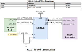
    The UART1 instance goes through a MUX (U70) to interface with the HSEC Connector. In order to have the mux in the "B2" mode then the select line will need to be high. There is an external pull down resistor on the select line to have the LIN mode phy signal routing selected by default. 

    To send UART signals to the docking station using the UART1 instance you will have to do the following steps:

    1. Write an I2C command to the IO expander to enable the LIN_MUX_SEL output.
    2. The default output state will be high and so no further configuration is needed.
    3. With the select line high, UART1 will now route to the HSEC connector. 

    Attached is example project that will configure the IO expander over I2C to set LIN_MUX_SEL high.

    AM263xCC_IOEXP_LIN_MUX_SEL.zip

    Please let me know if you have any further questions.

    Regards,

    Erik

  • Hello,

    As mentioned earlier, the goal is to use the Rx and Tx pins on the TMDSHSECDOCK (pins 76 and 78). To do this, I understand that I need to enable UART 1, hence the request to do it via I2C using the IO expander. However, I am not clear on how this works. I took your projects with the I2C, added a UART on pins L3 and M3 of the Sitara using sysconfig, and wrote a simple character echo code. When I use the USB port to check the UART (using Putty for visualization), I understand that it tests UART 0, and the echo code works. However, I am unable to read anything with the Rx and Tx pins. I tried connecting them to the Rx and Tx pins of an LP-CC2652RB (which is the ultimate goal), but I don't receive or send anything, or at least it doesn't seem so. As a final test, I connected pin Rx (76) to pin Tx (78) of the Sitara with the character echo code, and when I type a character in Putty, it is echoed back, but only once (while I expected it to appear multiple times since it should be transmitted via UART 0 and UART 1, and therefore received immediately on the Rx of UART 1 since the two pins are connected).

    I also noticed that the voltage at pins 76 and 78 is always at 0V, and I'm not sure if this is normal.

    Can you help me again using these Rx and Tx pins please ?

    Thank you for your time and attention

    Théo

  • Hello Theo,

    added a UART on pins L3 and M3 of the Sitara using sysconfig

    The UART1 instance can be assigned to many different balls. In the instance that you are describing (HSEC 76 and 78), you will need to assign the UART1 signals to A9 and B9 respectively. By assigning the signals to L3 and M3, you are actually routing the signals to HSEC 161 (UART1_RXD) and HSEC 162 (UART1_TXD), this can be done if you do not want to have the signals require the IO expander configuration as it is a direct connection between the SoC Ball and HSEC. 

    For the Complete signal HSEC mapping, refer to the Control Card User guide: Table 4-24. E2 HSEC Pinout

    Regards,

    Erik

  • Hello,
    Thank you for your answers.
    Based on our previous conversation, if I understand correctly, I can use the UART echo project from the mcu_plus_sdk_am263x_08_06_00_34 SDK. I just need to modify the UART configuration in sysconfig and replace the pins with L3 and M3, and then I can simply connect to pins 161 and 162 of the TMDSHSECDOCK for the UART connection with the LP-CC2652RB ?

    I want to confirm that I don't need to make any changes to the I2C or IO expander in this scenario since the connection will be direct between the Sitara processor and the HSEC pins, and that I don't need to make any other changes of the UART configuration because I do not succed in it.

    Thank you for your assistance. I appreciate your help in clarifying this matter.

    Théo

  • Hello Theo,

    If you are using L3 and M3 then that is correct.

    UART configuration because I do not succed in it.

    Even when using the HSEC pins 161 and 162?

    Regards,

    Erik

  • Hello,
    Indeed even with pins 161 and 162.
    I think it is better if I describe you my whole beginning of project so that you can better understand.


    Hardware Configuration:
    I am working with an AM2634C device connected to the TMDSHSECDOCK dockstation. Additionally, I am using an LP-CC2652RB module, which houses a CC2652 chip.

    Software Development Kits (SDKs):
    For the AM2634C, I am using the "mcu_plus_sdk_am263x_08_06_00_34" SDK.
    For the CC2652, I am utilizing the "simplelink_wbms_sdk_2_00_02_23_eng" SDK.

    Project Overview:
    The objective of my project is to establish a UART connection between the AM2634C and the CC2652, as well as a UART connection between the AM2634C and the Putty software running on a PC connected to the board via USB.

    Work Completed So Far:
    To begin, I started with the "UARTecho" project for the AM2634C, and it works perfectly between the PC and the AM2634C. When a string of characters is entered in putty, it echoes back the same string.

    Similarly, the "UART2echo" project for the CC2653 also functions the same way.

    From my understanding, the CC2652 communicates via UART with the TM4C129 when the jumpers are connected to Rx and Tx. Therefore, I wanted to disconnect these jumpers and utilize the Rx and Tx pins (on the CC2652 side) to connect them to the AM2634C. Consequently, I modified the code to continuously transmit a string of characters (which works when viewed on Putty).

    Next, I added an additional UART interface to the AM2634C's "UARTecho" project using sysconfig, placing it on L3 and M3, so that it should map this signal to pins 161 and 162 on the dock. By connecting pins 161 and 162 to the Rx and Tx pins of the LP-CC2652RB (on the C22653 side), I expected the AM2634C to receive the continuously transmitted string from the CC2652 and echo it through its two UART interfaces: UART0 via USB and UART1 via Rx and Tx pins. However, when I launch Putty to observe the communication, it does not work as expected. While the echo via UART0 through USB is still functional, there is no trace of the continuously transmitted string from the CC2652.

    I have done numerous tests and variations, including swapping the roles of the two boards, but I have been unable to establish a visible UART connection between the two devices.

    Considering the information provided, I would greatly appreciate any insights or guidance you can offer to help me resolve this issue. If you require any additional details or code snippets, please do not hesitate to let me know.

    Thank you for your time and assistance.

    Best regards,
    Théo

  • I just checked with an oscillo and no signal is transmited to the pin 162

  • Hello Theo,

    Are you able to run a quick check for me:

    • Add a GPIO instance on L3 and M3
    • Write both GPIO signals to high
    • Confirm that you are able to observe the High signal on Pins 161 and 162 of the HSEC dock

    The code to write a gpio signal high is: 

    GPIO_setDirMode(<name>_BASE_ADDR, <name>_PIN, <name>_DIR);
    GPIO_pinWriteHigh(<name>_BASE_ADDR, <name>_PIN);

    where <name> is the name that is associated with the GPIO signal within SYSCONFIG. 

    Regards,

    Erik

  • Hello,

    Yes it works. I took the GPIO led blink project and changed the instances to L3 and M3 and I Pins 161 and 162 of the HSEC are correctly alternating between high and low.

    By the way, don't you have an already done project that uses UART on whatever pin of the HSEC ?

    Regards,

    Théo

  • Hello again,

    I just made a new test and it works !!!

    Thank you so much for your relevant and responsive help.

    Best regards,

    Théo

  • Hello Theo,

    I am glad that you were able to get your test to work. Do you mind sharing what solved your issue?

    Regards,

    Erik