This thread has been locked.

If you have a related question, please click the "Ask a related question" button in the top right corner. The newly created question will be automatically linked to this question.

SCI with DMA

Part Number: TMS570LC4357

Hello. 

I'm trying to receive and transmit with a SCI device using the DMA to transfer data to the RAM. In my operational case I will receive burst of data from others equipment to my SCI devices and I will poll in a period thread the received data (and maybe send some data too).

I’m facing two problems that concern the receiving part.

  1. First issue

    What I did:

    • Setup a dma transfer from the SCI device to a buffer. With elements of 8bits, one element per frame, the size of the buffer in bytes as the number of expected frame and auto-initialization.
    • Setup the SCI device in loopback mode and send data to SCI device using a DMA transfer.
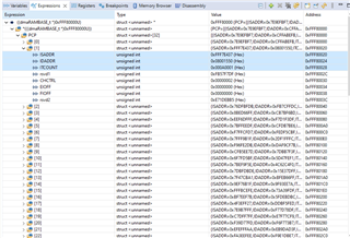
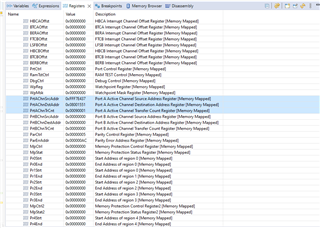
    • To retrieve received data, I read the CDADDR register.


    I observed that the value in the CDADDR register is always ‘late’ and do not point to the last transferred byte. In fact, the CDADDR register will not change until a new data burst is received.

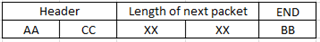
    The datasheet SPNU563A, explain about the Working Control packet that: “These bits are only updated after a channel is arbitrated out of the priority queue”.

    Therefore, I guess that the CDADDR register behavior is normal, but what is the correct way to received burst of data using the DMA?


    In this topic DMA working control packet semantics - Arm-based microcontrollers forum - Arm-based microcontrollers - TI E2E support forums, I saw that I could use the PAACDADDR register to determine the real last written address. In fact, this work but I am not sure that this is the right way to do things.

  2. Second issue

When the CDADDR register is up to date, I also observe a weird behavior. For example, a buffer of 10 bytes with addresses 0 to 9.

When the last burst of data fill the buffer until the address 8, then the CDADDR register point to the address 9.

When the last burst of data fill the buffer until the address 9, then the CDADDR register point to the address 9 too!


The only way a found to differentiate the two cases is with a BTC interruption. But again, I am not sure that this is the right way to do things.


Regards,
Jeff

  • Hi Jeff,

    I started working on your issue and i will provide an update ASAP.

    --

    Thanks & regards,
    Jagadish.

  • Hi Jeff,

    but what is the correct way to received burst of data using the DMA?

    Actually, it is not a good practice to use DMA for to receive unknown length burst packet. We can use DMA effectively only when we know the length of the packet.

    You can refer below thread here i mentioned how to use PAA registers to find the length of unknow size packet:

    (+) TMS570LC4357: What is the correct mechanism to use when receiving a data stream of unknown size bursts on an SCI link? - Arm-based microcontrollers - INTERNAL forum - Arm-based microcontrollers - INTERNAL - TI E2E support forums

    Again, the problem here is, you don't know when exactly to process PAA registers because we don't get any interrupt after immediately receiving burst packet data right, if it is a known length packet at least we can use block completion interrupt of DMA to process the packet.

    If you still want to use DMA for to receive unknown length packet you can do below method:

    you have to implement some protocol in application level, like the transmitter should needs to tell the receiver about the packet size it is going to send(this packet length is fixed), and receiver can change the DMA packet settings for the new packet size. In this way you can receive variable size of data using UART with DMA. Once it receives unknown length packet again it should need to change DMA packet settings to the known length packet to receive next unknown length of the packet and should continue the process.

    Example:

    Consider UART transmitter will send below packet to receiver before sending the unknown length packet:

    So, first i will initialize DMA with size of 5 elements, so whenever i received above packet the DMA will raise the block complete interrupt to the CPU now CPU will decode the above packet and finds the length of the next packet to be received. So now DMA will reconfigure its control fields to receive the next packet.

    --

    Thanks & regards,
    Jagadish.

  • Hello.
    Your link doesn't work.

    Jeff

  • Hi Jeff,

    Refer below pdf

    SCI with DMA for unknown length receive packet.pdf

    --

    Thanks & regards,
    Jagadish.

  • Hello.


    I am a little disappointed by your response. A DMA must be versatile as it could be use with any communication peripheral. When you are using COTS (for example a sensor), you cannot change the communication protocol, and receiving burst of variable length data is nothing fancy.

    An another common usage of a DMA is receiving data from an Ethernet port, network packet are burst of variable length data.


    So, I understand that using CDADDR and PAA register in the only way to solve my first problem. OK.


    However, you didn’t answered about my second issue.


    Regards,

    Jeff

  • Hello Jeff,

    Apologies for the delay.

    However, you didn’t answered about my second issue.

    I just need to test this behavior and analyze it. I will do that ASAP.

    --

    Thanks & regards,
    Jagadish.

  • Hi Jeff,

    When the CDADDR register is up to date, I also observe a weird behavior.

    As we discussed we don't know when exactly CDADDR register will have updated content right. I mean this register will get update only when arbitration happens, so don't use this register for data calculation.

    Instead of this why don't you use Port/FIFO registers for data calculations?

    I tested this Port/FIFO registers and they are updating as expected only.

    For example:

    1. This is my primary control packet. Here i am trying to send 10 elements and 1 frame, that is why ITCOUNT register have 0x000A(elements) and 0x0001(Frames).

    2. This is the Port/FIFO registers after sending one character.

    Here you can see TrCnt register value as 0x0009(remaining elements) and 0x0001(remaining frames)

    3. This is the Port/FIFO registers after sending five characters.

    Here HBC interrupt triggered and also TrCnt register value as 0x0005(remaining elements) and 0x0001(remaining frames).

    4. This is the Port/FIFO registers after sending nine characters.

    TrCnt register value as 0x0001(remaining elements) and 0x0001(remaining frames).

    5. This is the Port/FIFO registers after sending ten characters.

    Now BTC flag also set, and TrCnt register value as 0x0000(remaining elements) and 0x0000(remaining frames).

    So, i would suggest you to use these registers for to know how many elements transferred by DMA instead of CDADDR register.

    --

    Thanks & regards,
    Jagadish.