This thread has been locked.

If you have a related question, please click the "Ask a related question" button in the top right corner. The newly created question will be automatically linked to this question.

TM4C1290NCPDT: General-Purpose Mode for TM4C1290NCPDT

Part Number: TM4C1290NCPDT

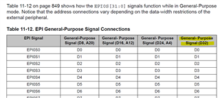
I am porting a legacy design from an AT91R40008. It has a very good External Peripheral Interface. I have 5 devices for the TI EPI Interface. One requires 16bit access and four require 8bit.. The only option appears to be the General-Purpose mode, using the address lines to enable the chips.

Can I map each range for the correct (and different bit access) and make it available at the same time? 

Is there any example code that shows how to configure this?

  • Can I map each range for the correct (and different bit access) and make it available at the same time? 

    Hi,

     Yes, according to the datasheet, the general-purpose mode can support up to 32bit. If you have 4 devices of 8-bit each, you can access these four devices in parallel at the same time. You could potentially use 4-bit address mode. Here you will have 24 bits of data lines available. With 24 bit data lines, you can connect one 16-bit device and one 8-bit device in parallel for one address range and three other 8-bit devices in parallel for another address range.  

    General-Purpose mode is designed for three general types of use:


    ■ Extremely high-speed clocked interfaces to FPGAs and CPLDs. Three sizes of data and optional
    address are supported. Framing and clock-enable functions permit more optimized interfaces.


    General parallel GPIO. From 1 to 32 pins may be written or read, with the speed precisely
    controlled by the EPIBAUD register baud rate (when used with the WFIFO and/or the NBRFIFO)
    or by the rate of accesses from software or μDMA. Examples of this type of use include:

    – Reading 20 sensors at fixed time periods by configuring 20 pins to be inputs, configuring the
    COUNT0 field in the EPIBAUD register to some divider, and then using non-blocking reads.
    – Implementing a very wide ganged PWM/PCM with fixed frequency for driving actuators, LEDs,
    etc.

    ■ General custom interfaces of any speed.

    Is there any example code that shows how to configure this?

    We do not have a general-purpose mode example. The only thing we have is a sdram mode that you can find in C:\ti\TivaWare_C_Series-2.2.0.295\examples\peripherals\epi. You can take a look of it and adapt it to general-purpose mode. 

  • Ok, if I understand this properly, so the direct answer is No, there is only one mappable block. The best option (if possible) would be 3 16bit ranges masking the byte needed on the last 4.devices. 

    Is there another TI arm part that can do this that is similar to the TM4C?

  • The best option (if possible) would be 3 16bit ranges masking the byte needed on the last 4.devices. 

    Yes, your understanding is correct. 

    Is there another TI arm part that can do this that is similar to the TM4C?

    I can't really speak for other TI MCU/MPU products. You are talking about accessing 5 devices in parallel for a total of 16 + 4*8 = 48 bits of data. I really doubt there is a device for that. Can AT91R40008 really do that? Reading its block diagram, it looks like it can only support 16 bits of data. Of course, I don't have the knowledge to know what is actually achievable with this third party device.

  • It's possible on the AT91R40008  because the EPI allows multiple blocks to be assigned to the address space at different bit widths. Actually a decent interface lost to history. 'twas the rage at the time.

    The parallel access won't work at all with the endpoint devices address decode would conflict with access to the 4 interrupt sources...

    The alternative now would be a 16bit data bus with and using A1-A3 to access a "byte" on a word boundary. or register addressing. Then it  would look "transparent".