This thread has been locked.
If you have a related question, please click the "Ask a related question" button in the top right corner. The newly created question will be automatically linked to this question.
Hi team,
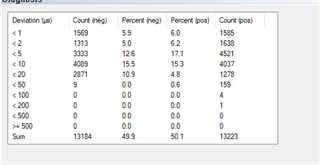
1)Using the Beckhoff SCC Demo, the FreeRTOS task is used to simulate the PDI and Syn0 interrupts, it seems that the DC function of EtherCAT can be implemented, but it don't work properly with the DC function, Sync Error for 1C32/1C33.20, there are errors, and the DC sync jitter is very large, essentially greater than 500us.
The customer then replaced it with a real PDI and Syn0 interrupt and found that in DC sync mode, the PDI interrupt could occur continuously while the Syn0 interrupt only occurs once. It doesn't come up anymore. Why;s this and how to get the Syn0 interrupt to occur continuously?
2) When using the DC function, continuously monitor the DC system clock of 0x0910 for EtherCAT and see that this clock can initially be the same as TwinCAT's PC clock, but will be about 20 seconds faster than the PC clock after 10 minutes of operation. The longer the time, the faster.
Could you help check this case? Thanks.
Best Regards,
Cherry
Hi
I have few questions :
1. Which SDK version are you using here?
2. Have you modified the stack code, or is it as it is after following steps from https://software-dl.ti.com/mcu-plus-sdk/esd/AM243X/08_06_00_43/exports/docs/api_guide_am243x/EXAMPLES_INDUSTRIAL_COMMS_ETHERCAT_SLAVE_BECKHOFF_SSC_DEMO.html#autotoc_md1248 ?
Regards
Dhaval
Hi Dhaval,
Thank you for the support.
1. Which SDK version are you using here?
It's 8.06.00.45.
2. Have you modified the stack code, or is it as it is after following steps from https://software-dl.ti.com/mcu-plus-sdk/esd/AM243X/08_06_00_43/exports/docs/api_guide_am243x/EXAMPLES_INDUSTRIAL_COMMS_ETHERCAT_SLAVE_BECKHOFF_SSC_DEMO.html#autotoc_md1248 ?
Customer follows the tutorial to modify, syn0 interrupt only once. The FreeRTOS system does a task in a way that does not allow for true synchronization because of task polling. DC clock jitter is above 500 us.
PRUICSS_waitEvent((PRUICSS_Handle)arg, evtOutNum); the event signal obtained by this function is also false. A success signal is returned directly, which is independent of the Syn0 interrupt.
Thanks and regards,
Cherry
Hi Cherry,
We are looking into this issue, please allow us sometime to get back on it by early next week.
Hi Nilabh,
May I know is there any suggestion for above question?
Regards,
Annie
Hi Annie,
Apologies for th delay. Due to internal priorities, we have not been look into the issue, I will be prioritizing on looking into it this week. Will update you by tomorrow.
Hi Cherry,
From our tests we see no issue with Sync0 Interrupt. What do you mean by real sync 0 interrupt, Could you please share more details?
1. Followed the steps mentioned here: AM243x MCU+ SDK: EtherCAT SubDevice Setup with TwinCAT (ti.com)
2. Enabled sync 0 and Sync 1
3. We could see sync0 ISR hitting everytime and sync pulse is also being generated (SYNC0 and SYNC1)
You see the results below:
Hi Nilabh,
The sample being used is last year's XAM2434ASFGGAALX, would you share what type of chip is being used at your end? Is it going to be a issue?
Thanks and regards,
Cherry
Hi Cherry,
The sample being used is last year's XAM2434ASFGGAALX, would you share what type of chip is being used at your end? Is it going to be a issue?
I am using E3 revision of AM243-LP. It has F part number. It does not seem be a part number issue. More of a application related issue. Is it possible to share the example project which customer is using.
Hi Nilabh,
Would it be possible to share a test sample project for the AM243-LP development board?
I'm trying to get the example project at the customer end and please give me some time.
Thanks and regards,
Cherry
Hi Cherry,
I cannot share the example project as It needs Beckoff ETG stack to build. If customer has a beckoff EtherCAT stack, then they can simply follow the instruction here: software-dl.ti.com/.../EXAMPLES_INDUSTRIAL_COMMS_ETHERCAT_SLAVE_BECKHOFF_SSC_DEMO.html
and build the project. I have also followed the same.
Hi Nilabh,
Thank you.
BspInitParams-> enhancedlink_enable to TIESC_MDIO_RX_link_disable should be this: bspInitParams-> enhancedlink_enable to TIESC_MDIO_RX_link_enable.
When tested in OSPI boot mode, exit after each test and then press normal debug without entering, you must re-program the bootloader before you can do so. Finally, it was successfully entered using load_DMSC.js mode, but it was found that the 0x60000000 locations of OSPI-Flash all changed to "E".
MAIN_Cortex_R5_0_0: GEL Output: CPU reset (soft reset) has been issued through GEL.
MAIN_Cortex_R5_0_0: Trouble Writing Memory Block at 0x0 on Page 0 of Length 0x40: (Error -1065 @ 0x40) Unable to access device memory. Verify that the memory address is in valid memory. If error persists, confirm configuration, power-cycle board, and/or try more reliable JTAG settings (e.g. lower TCLK). (Emulation package 9.10.0.00080)
MAIN_Cortex_R5_0_0: File Loader: Verification failed: Target failed to write 0x00000000
MAIN_Cortex_R5_0_0: GEL: File: ****.out: Load failed.
Normally, there should be boot data, as follows:
Thanks and regards,
Cherry
Hi,
Also there's one more finding, for the newly released AM2432BSEFHIALXR chip, it has to be set to bspInitParams->enhancedlink_enable=TIESC_MDIO_RX_LINK_DISABLE, MDIO_MANUAL_MODE_ENABLED cannot be defined.
But regarding AM243-LP E2, you must set to bspInitParams->enhancedlink_enable=TIESC_MDIO_RX_LINK_ENABLE. MDIO_MANUAL_MODE_ENABLED must be defined. Is there any specific reason?
Thanks and regards,
Cherry
Let me check this, does this help with the previous jitter you were observing?
When tested in OSPI boot mode, exit after each test and then press normal debug without entering, you must re-program the bootloader before you can do so. Finally, it was successfully entered using load_DMSC.js mode, but it was found that the 0x60000000 locations of OSPI-Flash all changed to "E".
Hi Cherry,
Can you share your test setup information mentioning how were you intending to work with ?
Best Regards,
Aakash
Hi Nilabh and Aakash,
does this help with the previous jitter you were observing?
Jitter has improved, mostly within 100 us, and a majority above 100 us, changing task cycles to 20ms:
Can you share your test setup information mentioning how were you intending to work with ?
This issue occurs on the AM243x-LP E2 development board using the XAM2434ASFGG sample. Burning SBL_osPI.release.tiimage and then debugging the program in QSPI boot mode.
Follow the guidelines(https://software-dl.ti.com/mcu-plus-sdk/esd/AM243X/latest/exports/docs/api_guide_am243x/EXAMPLES_INDUSTRIAL_COMMS_ETHERCAT_SLAVE_BECKHOFF_SSC_DEMO.html) on custom PCBs developed with the newly released AM2432BSEFHIALXR chip, it worked.
Thanks and regards,
Cherry
Follow the guidelines(https://software-dl.ti.com/mcu-plus-sdk/esd/AM243X/latest/exports/docs/api_guide_am243x/EXAMPLES_INDUSTRIAL_COMMS_ETHERCAT_SLAVE_BECKHOFF_SSC_DEMO.html) on custom PCBs developed with the newly released AM2432BSEFHIALXR chip, it worked.
Ok Glad to hear that Cherry.
Also I would recommend that having a separate issue for the ospi issue will make it easier for us to respond. Could you please create another thread for it. And have only ethercat based question on this thread.
Hi Nilabh,
Follow the guidelines(https://software-dl.ti.com/mcu-plus-sdk/esd/AM243X/latest/exports/docs/api_guide_am243x/EXAMPLES_INDUSTRIAL_COMMS_ETHERCAT_SLAVE_BECKHOFF_SSC_DEMO.html) on custom PCBs developed with the newly released AM2432BSEFHIALXR chip, it worked.Ok Glad to hear that Cherry.
Thank you and just want to make sure is the issue due to a large change in the latest released chip from past sample designs or any other possible reason?
Also I would recommend that having a separate issue for the ospi issue will make it easier for us to respond. Could you please create another thread for it. And have only ethercat based question on this thread.
I've created a related thread for OSPI issue and please see the link here:
Thanks and regards,
Cherry
Thanks Cherry,
Thank you and just want to make sure is the issue due to a large change in the latest released chip from past sample designs or any other possible reason?
I need to check this and get back by next week.