This thread has been locked.

If you have a related question, please click the "Ask a related question" button in the top right corner. The newly created question will be automatically linked to this question.

AM2434: FLASH integration with AM2434

Part Number: AM2434

Hi Team,

I have custom board of AM2434 and interfacing it with SFDP supported 1GB quad FLASH.

I have successfully implemented "ospi_flash_diag_am2434" and got all the data, then tried with "ospi_flash_dma_am2434" with DMA enabled, PHY disabled and D0-D3 data pin.

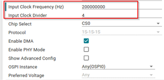
First i have implemented 1S-1S-1S protocol successfully as per the following image

then i tried with 1S-1S-2S and 4S-4S-4S but it stuck in infinite loop. Then after that again i tried with 1S-1S-1S , that protocol also no working, getting following error.

[MAIN_Cortex_R5_0_0] [OSPI] DMA low latency example started...
ERROR: App_OspiFlashDmaCompareBuffers:434: OSPI read data mismatch at index 1 !!!
OSPI Write 32 bytes in 44216 ns
OSPI Read 32 bytes in 5805 ns
OSPI Read 32 bytes in 0 ns
Average time for OSPI Read 32 bytes in 580 ns
Some tests have failed !!!

Same thing was happened before, at that time i did restart and process with diagnosed and dma code with that it was working with 1S-1S-1S. But now its not working

--

Thanks & Regards,

Divyesh Patel

  • Hi Divyesh.

    Maybe the SFDP table supported is not the same as the one expected.

    Try this FAQ - https://e2e.ti.com/support/microcontrollers/arm-based-microcontrollers-group/arm-based-microcontrollers/f/arm-based-microcontrollers-forum/1230063/faq-mcu-plus-sdk-am243x-faq-how-to-debug-develop-migrate-the-flash-driver-for-custom-flash-on-non-ti-evm-ospi-xspi

    This will walk through all the modes supported and what are the usual changes. Also it would be easier if you could also share the datasheet of your flash vendor so it becomes easier to support.

    Best Regards,
    Aakash

  • Hi Akash,

    Thank you for your response.

    Yes, I have referred.

    PFA datasheet and diagnosed data.

    1GB_MT25QL01GBBB.pdf

    [MAIN_Cortex_R5_0_0] [OSPI Flash Diagnostic Test] Starting ...
    [OSPI Flash Diagnostic Test] Flash Manufacturer ID : 0x20
    [OSPI Flash Diagnostic Test] Flash Device ID       : 0xBA21
    [OSPI Flash Diagnostic Test] Executing Flash Erase on first block...
    [OSPI Flash Diagnostic Test] Done !!!
    [OSPI Flash Diagnostic Test] Performing Write-Read Test...
    [OSPI Flash Diagnostic Test] Write-Read Test Passed!
    [QSPI Flash Diagnostic Test] SFDP Information : 
    ================================================
                          SFDP                      
    ================================================
    SFDP Major Revision                       : 0x1
    SFDP Minor Revision                       : 0x6
    Number of Parameter Headers in this Table : 2
    
    Types of Additional Parameter Tables in this flash
    ---------------------------------------------------
    4 BYTE ADDRESSING MODE INSTRUCTIONS TABLE
    JSON Data for the flash :
    
    {
    
    	"flashSize": 134217728,
    	"flashPageSize": 256,
    	"flashManfId": "0x20",
    	"flashDeviceId": "0xBA21",
    	"flashBlockSize": 65536,
    	"flashSectorSize": 4096,
    	"cmdBlockErase3B": "0xD8",
    	"cmdBlockErase4B": "0xDC",
    	"cmdSectorErase3B": "0x20",
    	"cmdSectorErase4B": "0x21",
    	"protos": {
    		"p111": {
    			"isDtr": false,
    			"cmdRd": "0x03",
    			"cmdWr": "0x02",
    			"modeClksCmd": 0,
    			"modeClksRd": 0,
    			"dummyClksCmd": 0,
    			"dummyClksRd": 0,
    			"enableType": "0",
    			"enableSeq": "0x00",
    			"dummyCfg": null,
    			"protoCfg": null,
    			"strDtrCfg": null
    		},
    		"p112": {
    			"isDtr": false,
    			"cmdRd": "0x3C",
    			"cmdWr": "0x02",
    			"modeClksCmd": 0,
    			"modeClksRd": 1,
    			"dummyClksCmd": 0,
    			"dummyClksRd": 7,
    			"enableType": "0",
    			"enableSeq": "0x00",
    			"dummyCfg": null,
    			"protoCfg": null,
    			"strDtrCfg": null
    		},
    		"p114": {
    			"isDtr": false,
    			"cmdRd": "0x6C",
    			"cmdWr": "0x34",
    			"modeClksCmd": 0,
    			"modeClksRd": 1,
    			"dummyClksCmd": 0,
    			"dummyClksRd": 7,
    			"enableType": "0",
    			"enableSeq": "0x00",
    			"dummyCfg": null,
    			"protoCfg": null,
    			"strDtrCfg": null
    		},
    		"p118": {
    			"isDtr": false,
    			"cmdRd": "0x7C",
    			"cmdWr": "0x84",
    			"modeClksCmd": 0,
    			"modeClksRd": 0,
    			"dummyClksCmd": 0,
    			"dummyClksRd": 0,
    			"enableType": "255",
    			"enableSeq": "0x00",
    			"dummyCfg": null,
    			"protoCfg": null,
    			"strDtrCfg": null
    		},
    		"p444s": {
    			"isDtr": false,
    			"cmdRd": "0xEB",
    			"cmdWr": "0x02",
    			"modeClksCmd": 0,
    			"modeClksRd": 1,
    			"dummyClksCmd": 0,
    			"dummyClksRd": 9,
    			"enableType": "0",
    			"enableSeq": "0x14",
    			"dummyCfg": {
    				"isAddrReg": false,
    				"cmdRegRd":"0x00",
    				"cmdRegWr":"0x00",
    				"cfgReg":"0x00000000",
    				"shift":0,
    				"mask":"0x00",
    				"bitP":0
    			},
    			"protoCfg": {
    				"isAddrReg": false,
    				"cmdRegRd": "0x00",
    				"cmdRegWr": "0x00",
    				"cfgReg": "0x00000000",
    				"shift": 0,
    				"mask": "0x00",
    				"bitP": 0
    			},
    			"strDtrCfg": {
    				"isAddrReg": false,
    				"cmdRegRd": "0x00",
    				"cmdRegWr": "0x00",
    				"cfgReg": "0x00000000",
    				"shift": 0,
    				"mask": "0x00",
    				"bitP": 0
    			}
    		},
    		"p444d": {
    			"isDtr": false,
    			"cmdRd": "0xEB",
    			"cmdWr": "0x02",
    			"modeClksCmd": 0,
    			"modeClksRd": 1,
    			"dummyClksCmd": 0,
    			"dummyClksRd": 9,
    			"enableType": "0",
    			"enableSeq": "0x14",
    			"dummyCfg": {
    				"isAddrReg": false,
    				"cmdRegRd":"0x00",
    				"cmdRegWr":"0x00",
    				"cfgReg":"0x00000000",
    				"shift":0,
    				"mask":"0x00",
    				"bitP":0
    			},
    			"protoCfg": {
    				"isAddrReg": false,
    				"cmdRegRd": "0x00",
    				"cmdRegWr": "0x00",
    				"cfgReg": "0x00000000",
    				"shift": 0,
    				"mask": "0x00",
    				"bitP": 0
    			},
    			"strDtrCfg": {
    				"isAddrReg": false,
    				"cmdRegRd": "0x00",
    				"cmdRegWr": "0x00",
    				"cfgReg": "0x00000000",
    				"shift": 0,
    				"mask": "0x00",
    				"bitP": 0
    			}
    		},
    		"p888s": null,
    		"p888d": null,
    		"pCustom": { 
    			"fxn": null
    		}
    	},
    	"addrByteSupport": "1",
    	"fourByteAddrEnSeq": "0x36",
    	"cmdExtType": "NONE",
    	"resetType": "0x3D",
    	"deviceBusyType": "0",
    	"cmdWren": "0x06",
    	"cmdRdsr": "0x05",
    	"srWip":  0,
    	"srWel":  0,
    	"cmdChipErase": "0xC7",
    	"rdIdSettings": {
    		"cmd": "0x9F",
    		"numBytes": 5,
    		"dummy4": 0,
    		"dummy8": 0
    	},
    	"xspiWipRdCmd": "0x00",
    	"xspiWipReg": "0x00000000",
    	"xspiWipBit": 0,
    	"flashDeviceBusyTimeout": 128000000,
    	"flashPageProgTimeout": 120
    }
    
    All tests have passed!!
    

    --

    Thanks & Regards,

    Divyesh Patel

  • Hi Divyesh,

    Can you share your syscfg for the same ?

    Best Regards,
    Aakash

  • Hi Akash,

    PFA details.

    /**
     * These arguments were used when this file was generated. They will be automatically applied on subsequent loads
     * via the GUI or CLI. Run CLI with '--help' for additional information on how to override these arguments.
     * @cliArgs --device "AM243x_ALV_beta" --package "ALV" --part "ALV" --context "r5fss0-0" --product "MCU_PLUS_SDK_AM243x@08.06.00"
     * @versions {"tool":"1.14.0+2667"}
     */
    
    /**
     * Import the modules used in this configuration.
     */
    const flash      = scripting.addModule("/board/flash/flash", {}, false);
    const flash1     = flash.addInstance();
    const udma       = scripting.addModule("/drivers/udma/udma", {}, false);
    const udma1      = udma.addInstance();
    const clock      = scripting.addModule("/kernel/dpl/clock");
    const debug_log  = scripting.addModule("/kernel/dpl/debug_log");
    const mpu_armv7  = scripting.addModule("/kernel/dpl/mpu_armv7", {}, false);
    const mpu_armv71 = mpu_armv7.addInstance();
    const mpu_armv72 = mpu_armv7.addInstance();
    const mpu_armv73 = mpu_armv7.addInstance();
    const mpu_armv74 = mpu_armv7.addInstance();
    const mpu_armv75 = mpu_armv7.addInstance();
    
    /**
     * Write custom configuration values to the imported modules.
     */
    flash1.$name                           = "CONFIG_FLASH0";
    flash1.flashSize                       = 134217728;
    flash1.flashManfId                     = "0x20";
    flash1.flashDeviceId                   = "0xBA21";
    flash1.flashBlockSize                  = 65536;
    flash1.cmdBlockErase3B                 = "0xD8";
    flash1.cmdSectorErase3B                = "0x20";
    flash1.dummyClksCmd                    = 0;
    flash1.dummy_isAddrReg                 = false;
    flash1.device                          = "CUSTOM_FLASH";
    flash1.fname                           = "MT25G01";
    flash1.proto_isAddrReg                 = false;
    flash1.strDtr_isAddrReg                = false;
    flash1.cmdWr                           = "0x02";
    flash1.cmdRd                           = "0x03";
    flash1.dummyClksRd                     = 0;
    flash1.protocol                        = "1s_1s_1s";
    flash1.peripheralDriver.$name          = "CONFIG_OSPI0";
    flash1.peripheralDriver.dmaEnable      = true;
    flash1.peripheralDriver.baudRateDiv    = 2;
    flash1.peripheralDriver.OSPI.DQS.$used = false;
    flash1.peripheralDriver.OSPI.D7.rx     = false;
    flash1.peripheralDriver.OSPI.D7.$used  = false;
    flash1.peripheralDriver.OSPI.D6.rx     = false;
    flash1.peripheralDriver.OSPI.D6.$used  = false;
    flash1.peripheralDriver.OSPI.D5.rx     = false;
    flash1.peripheralDriver.OSPI.D5.$used  = false;
    flash1.peripheralDriver.OSPI.D4.rx     = false;
    flash1.peripheralDriver.OSPI.D4.$used  = false;
    
    udma1.$name                        = "CONFIG_UDMA0";
    flash1.peripheralDriver.udmaDriver = udma1;
    udma1.udmaBlkCopyChannel.create(1);
    udma1.udmaBlkCopyChannel[0].$name  = "CONFIG_UDMA_BLKCOPY_CH0";
    
    debug_log.enableUartLog        = true;
    debug_log.uartLog.$name        = "CONFIG_UART_LOG";
    debug_log.uartLog.UART.$assign = "USART0";
    
    mpu_armv71.$name             = "CONFIG_MPU_REGION0";
    mpu_armv71.size              = 31;
    mpu_armv71.attributes        = "Device";
    mpu_armv71.accessPermissions = "Supervisor RD+WR, User RD";
    mpu_armv71.allowExecute      = false;
    
    mpu_armv72.$name             = "CONFIG_MPU_REGION1";
    mpu_armv72.size              = 15;
    mpu_armv72.accessPermissions = "Supervisor RD+WR, User RD";
    
    mpu_armv73.$name             = "CONFIG_MPU_REGION2";
    mpu_armv73.baseAddr          = 0x41010000;
    mpu_armv73.size              = 15;
    mpu_armv73.accessPermissions = "Supervisor RD+WR, User RD";
    
    mpu_armv74.$name             = "CONFIG_MPU_REGION3";
    mpu_armv74.baseAddr          = 0x70000000;
    mpu_armv74.size              = 21;
    mpu_armv74.accessPermissions = "Supervisor RD+WR, User RD";
    
    mpu_armv75.$name    = "CONFIG_MPU_REGION5";
    mpu_armv75.baseAddr = 0x80000000;
    mpu_armv75.size     = 31;
    
    /**
     * Pinmux solution for unlocked pins/peripherals. This ensures that minor changes to the automatic solver in a future
     * version of the tool will not impact the pinmux you originally saw.  These lines can be completely deleted in order to
     * re-solve from scratch.
     */
    flash1.peripheralDriver.OSPI.$suggestSolution      = "OSPI0";
    flash1.peripheralDriver.OSPI.CLK.$suggestSolution  = "ball.N20";
    flash1.peripheralDriver.OSPI.CSn0.$suggestSolution = "ball.L19";
    flash1.peripheralDriver.OSPI.D3.$suggestSolution   = "ball.M21";
    flash1.peripheralDriver.OSPI.D2.$suggestSolution   = "ball.M20";
    flash1.peripheralDriver.OSPI.D1.$suggestSolution   = "ball.M18";
    flash1.peripheralDriver.OSPI.D0.$suggestSolution   = "ball.M19";
    debug_log.uartLog.UART.RXD.$suggestSolution        = "ball.D15";
    debug_log.uartLog.UART.TXD.$suggestSolution        = "ball.C16";
    

    --

    Thanks & Regards,

    Divyesh Patel

  • Hi Divyesh,

    Can you try reducing the speed of the controller ? I think 50MHz would be apt speed for controller if its functioning at 1-1-1 mode without PHY.

    Best Regards,
    Aakash

  • Hi Akash,

    Can you try reducing the speed of the controller ? I think 50MHz would be apt speed for controller if its functioning at 1-1-1 mode without PHY.

    I tried with 50MHz, its working fine for 1S-1S-1S, but not for 1S-1S-2S with 1byte DMA data.

    [MAIN_Cortex_R5_0_0] [OSPI] DMA low latency example started...
    ERROR: App_OspiFlashDmaCompareBuffers:435: OSPI read data mismatch at index 0 !!!
    OSPI Write 1 bytes in 24693 ns
    OSPI Read 1 bytes in 7395 ns
    OSPI Read 1 bytes in 0 ns
    OSPI Read 1 bytes in 0 ns
    OSPI Read 1 bytes in 0 ns
    OSPI Read 1 bytes in 0 ns
    OSPI Read 1 bytes in 0 ns
    OSPI Read 1 bytes in 0 ns
    OSPI Read 1 bytes in 0 ns
    OSPI Read 1 bytes in 0 ns
    OSPI Read 1 bytes in 0 ns
    Average time for OSPI Read 1 bytes in 738 ns
    Some tests have failed !!!
    

    --

    Thanks & Regards,

    Divyesh Patel

  • Hi Divyesh,

    Can you share your non-working syscfg or just the changes done in between 1-1-1 and 1-1-2 ?

    Best Regards,
    Aakash

  • Hi Akash,

    Yeah Sure,

    Working 1S-1S-1S 

    /**
     * These arguments were used when this file was generated. They will be automatically applied on subsequent loads
     * via the GUI or CLI. Run CLI with '--help' for additional information on how to override these arguments.
     * @cliArgs --device "AM243x_ALV_beta" --package "ALV" --part "ALV" --context "r5fss0-0" --product "MCU_PLUS_SDK_AM243x@08.06.00"
     * @versions {"tool":"1.14.0+2667"}
     */
    
    /**
     * Import the modules used in this configuration.
     */
    const flash      = scripting.addModule("/board/flash/flash", {}, false);
    const flash1     = flash.addInstance();
    const udma       = scripting.addModule("/drivers/udma/udma", {}, false);
    const udma1      = udma.addInstance();
    const clock      = scripting.addModule("/kernel/dpl/clock");
    const debug_log  = scripting.addModule("/kernel/dpl/debug_log");
    const mpu_armv7  = scripting.addModule("/kernel/dpl/mpu_armv7", {}, false);
    const mpu_armv71 = mpu_armv7.addInstance();
    const mpu_armv72 = mpu_armv7.addInstance();
    const mpu_armv73 = mpu_armv7.addInstance();
    const mpu_armv74 = mpu_armv7.addInstance();
    const mpu_armv75 = mpu_armv7.addInstance();
    
    /**
     * Write custom configuration values to the imported modules.
     */
    flash1.$name                           = "CONFIG_FLASH0";
    flash1.flashSize                       = 134217728;
    flash1.flashManfId                     = "0x20";
    flash1.flashDeviceId                   = "0xBA21";
    flash1.flashBlockSize                  = 65536;
    flash1.cmdBlockErase3B                 = "0xD8";
    flash1.cmdSectorErase3B                = "0x20";
    flash1.dummyClksCmd                    = 0;
    flash1.dummy_isAddrReg                 = false;
    flash1.device                          = "CUSTOM_FLASH";
    flash1.fname                           = "MT25G01";
    flash1.strDtr_isAddrReg                = false;
    flash1.protocol                        = "1s_1s_1s";
    flash1.cmdRd                           = "0x03";
    flash1.cmdWr                           = "0x02";
    flash1.dummyClksRd                     = 0;
    flash1.peripheralDriver.$name          = "CONFIG_OSPI0";
    flash1.peripheralDriver.dmaEnable      = true;
    flash1.peripheralDriver.inputClkFreq   = 50000000;
    flash1.peripheralDriver.OSPI.DQS.$used = false;
    flash1.peripheralDriver.OSPI.D7.rx     = false;
    flash1.peripheralDriver.OSPI.D7.$used  = false;
    flash1.peripheralDriver.OSPI.D6.rx     = false;
    flash1.peripheralDriver.OSPI.D6.$used  = false;
    flash1.peripheralDriver.OSPI.D5.rx     = false;
    flash1.peripheralDriver.OSPI.D5.$used  = false;
    flash1.peripheralDriver.OSPI.D4.rx     = false;
    flash1.peripheralDriver.OSPI.D4.$used  = false;
    
    udma1.$name                        = "CONFIG_UDMA0";
    flash1.peripheralDriver.udmaDriver = udma1;
    udma1.udmaBlkCopyChannel.create(1);
    udma1.udmaBlkCopyChannel[0].$name  = "CONFIG_UDMA_BLKCOPY_CH0";
    
    debug_log.enableUartLog        = true;
    debug_log.uartLog.$name        = "CONFIG_UART_LOG";
    debug_log.uartLog.UART.$assign = "USART0";
    
    mpu_armv71.$name             = "CONFIG_MPU_REGION0";
    mpu_armv71.size              = 31;
    mpu_armv71.attributes        = "Device";
    mpu_armv71.accessPermissions = "Supervisor RD+WR, User RD";
    mpu_armv71.allowExecute      = false;
    
    mpu_armv72.$name             = "CONFIG_MPU_REGION1";
    mpu_armv72.size              = 15;
    mpu_armv72.accessPermissions = "Supervisor RD+WR, User RD";
    
    mpu_armv73.$name             = "CONFIG_MPU_REGION2";
    mpu_armv73.baseAddr          = 0x41010000;
    mpu_armv73.size              = 15;
    mpu_armv73.accessPermissions = "Supervisor RD+WR, User RD";
    
    mpu_armv74.$name             = "CONFIG_MPU_REGION3";
    mpu_armv74.baseAddr          = 0x70000000;
    mpu_armv74.size              = 21;
    mpu_armv74.accessPermissions = "Supervisor RD+WR, User RD";
    
    mpu_armv75.$name    = "CONFIG_MPU_REGION5";
    mpu_armv75.baseAddr = 0x80000000;
    mpu_armv75.size     = 31;
    
    /**
     * Pinmux solution for unlocked pins/peripherals. This ensures that minor changes to the automatic solver in a future
     * version of the tool will not impact the pinmux you originally saw.  These lines can be completely deleted in order to
     * re-solve from scratch.
     */
    flash1.peripheralDriver.OSPI.$suggestSolution      = "OSPI0";
    flash1.peripheralDriver.OSPI.CLK.$suggestSolution  = "ball.N20";
    flash1.peripheralDriver.OSPI.CSn0.$suggestSolution = "ball.L19";
    flash1.peripheralDriver.OSPI.D3.$suggestSolution   = "ball.M21";
    flash1.peripheralDriver.OSPI.D2.$suggestSolution   = "ball.M20";
    flash1.peripheralDriver.OSPI.D1.$suggestSolution   = "ball.M18";
    flash1.peripheralDriver.OSPI.D0.$suggestSolution   = "ball.M19";
    debug_log.uartLog.UART.RXD.$suggestSolution        = "ball.D15";
    debug_log.uartLog.UART.TXD.$suggestSolution        = "ball.C16";
    

    1S-1S-4S which is not working

    /**
     * These arguments were used when this file was generated. They will be automatically applied on subsequent loads
     * via the GUI or CLI. Run CLI with '--help' for additional information on how to override these arguments.
     * @cliArgs --device "AM243x_ALV_beta" --package "ALV" --part "ALV" --context "r5fss0-0" --product "MCU_PLUS_SDK_AM243x@08.06.00"
     * @versions {"tool":"1.14.0+2667"}
     */
    
    /**
     * Import the modules used in this configuration.
     */
    const flash      = scripting.addModule("/board/flash/flash", {}, false);
    const flash1     = flash.addInstance();
    const udma       = scripting.addModule("/drivers/udma/udma", {}, false);
    const udma1      = udma.addInstance();
    const clock      = scripting.addModule("/kernel/dpl/clock");
    const debug_log  = scripting.addModule("/kernel/dpl/debug_log");
    const mpu_armv7  = scripting.addModule("/kernel/dpl/mpu_armv7", {}, false);
    const mpu_armv71 = mpu_armv7.addInstance();
    const mpu_armv72 = mpu_armv7.addInstance();
    const mpu_armv73 = mpu_armv7.addInstance();
    const mpu_armv74 = mpu_armv7.addInstance();
    const mpu_armv75 = mpu_armv7.addInstance();
    
    /**
     * Write custom configuration values to the imported modules.
     */
    flash1.$name                           = "CONFIG_FLASH0";
    flash1.flashSize                       = 134217728;
    flash1.flashManfId                     = "0x20";
    flash1.flashDeviceId                   = "0xBA21";
    flash1.flashBlockSize                  = 65536;
    flash1.cmdBlockErase3B                 = "0xD8";
    flash1.cmdSectorErase3B                = "0x20";
    flash1.dummyClksCmd                    = 0;
    flash1.dummy_isAddrReg                 = false;
    flash1.device                          = "CUSTOM_FLASH";
    flash1.fname                           = "MT25G01";
    flash1.strDtr_isAddrReg                = false;
    flash1.protocol                        = "1s_1s_4s";
    flash1.cmdRd                           = "0x6C";
    flash1.cmdWr                           = "0x34";
    flash1.modeClksRd                      = 1;
    flash1.dummyClksRd                     = 7;
    flash1.peripheralDriver.$name          = "CONFIG_OSPI0";
    flash1.peripheralDriver.dmaEnable      = true;
    flash1.peripheralDriver.inputClkFreq   = 50000000;
    flash1.peripheralDriver.OSPI.DQS.$used = false;
    flash1.peripheralDriver.OSPI.D7.rx     = false;
    flash1.peripheralDriver.OSPI.D7.$used  = false;
    flash1.peripheralDriver.OSPI.D6.rx     = false;
    flash1.peripheralDriver.OSPI.D6.$used  = false;
    flash1.peripheralDriver.OSPI.D5.rx     = false;
    flash1.peripheralDriver.OSPI.D5.$used  = false;
    flash1.peripheralDriver.OSPI.D4.rx     = false;
    flash1.peripheralDriver.OSPI.D4.$used  = false;
    
    udma1.$name                        = "CONFIG_UDMA0";
    flash1.peripheralDriver.udmaDriver = udma1;
    udma1.udmaBlkCopyChannel.create(1);
    udma1.udmaBlkCopyChannel[0].$name  = "CONFIG_UDMA_BLKCOPY_CH0";
    
    debug_log.enableUartLog        = true;
    debug_log.uartLog.$name        = "CONFIG_UART_LOG";
    debug_log.uartLog.UART.$assign = "USART0";
    
    mpu_armv71.$name             = "CONFIG_MPU_REGION0";
    mpu_armv71.size              = 31;
    mpu_armv71.attributes        = "Device";
    mpu_armv71.accessPermissions = "Supervisor RD+WR, User RD";
    mpu_armv71.allowExecute      = false;
    
    mpu_armv72.$name             = "CONFIG_MPU_REGION1";
    mpu_armv72.size              = 15;
    mpu_armv72.accessPermissions = "Supervisor RD+WR, User RD";
    
    mpu_armv73.$name             = "CONFIG_MPU_REGION2";
    mpu_armv73.baseAddr          = 0x41010000;
    mpu_armv73.size              = 15;
    mpu_armv73.accessPermissions = "Supervisor RD+WR, User RD";
    
    mpu_armv74.$name             = "CONFIG_MPU_REGION3";
    mpu_armv74.baseAddr          = 0x70000000;
    mpu_armv74.size              = 21;
    mpu_armv74.accessPermissions = "Supervisor RD+WR, User RD";
    
    mpu_armv75.$name    = "CONFIG_MPU_REGION5";
    mpu_armv75.baseAddr = 0x80000000;
    mpu_armv75.size     = 31;
    
    /**
     * Pinmux solution for unlocked pins/peripherals. This ensures that minor changes to the automatic solver in a future
     * version of the tool will not impact the pinmux you originally saw.  These lines can be completely deleted in order to
     * re-solve from scratch.
     */
    flash1.peripheralDriver.OSPI.$suggestSolution      = "OSPI0";
    flash1.peripheralDriver.OSPI.CLK.$suggestSolution  = "ball.N20";
    flash1.peripheralDriver.OSPI.CSn0.$suggestSolution = "ball.L19";
    flash1.peripheralDriver.OSPI.D3.$suggestSolution   = "ball.M21";
    flash1.peripheralDriver.OSPI.D2.$suggestSolution   = "ball.M20";
    flash1.peripheralDriver.OSPI.D1.$suggestSolution   = "ball.M18";
    flash1.peripheralDriver.OSPI.D0.$suggestSolution   = "ball.M19";
    debug_log.uartLog.UART.RXD.$suggestSolution        = "ball.D15";
    debug_log.uartLog.UART.TXD.$suggestSolution        = "ball.C16";
    

    --

    Thanks & Regards,

    Divyesh Patel

  • Hi Divyesh,

    Are you really following the FAQ ? Everything explicitly mentioned is not followed religiously.

    The list of issues with your configurations --

    1. You have changed the Program command to Fast Program over 4 data lines. I am not sure if that is even supported or not.

    You should be using 4-BYTE PAGE PROGRAM (12h) only because you have enabled 4 Byte Addressing.


    2. You have some quirks function defined. This is not right. You should keep it as NULL. Please check the FAQ.


    3. Protocol Configuration is set as enabled and Dummy Cycles configured is not configured at all.

    You should be writing into the volatile config registers to configure the dummy configurations.

    And the 0x71 does not seem like a valid command to write anyways.


    4. Enable 4 byte Addressing is incorrect --


    5. You should also be doing this configuration -

    As this is very custom implementation, you need to modify the driver/flash open function i.e. Flash_norOspiOpen or Flash_setQeBit to call status = Flash_norOspiCmdWrite(config, 0x35, OSPI_CMD_INVALID_ADDR, 0, NULL, 0);

    So the device enters the quad mode.

    Again, my strong recommendation is to follow the FAQ.

    Best Regards,
    Aakash

  • HI Aakash,

    Actually by following FAQ whichever configurable term was there, i tried to edit that only. I didn't get rest of the term and its use and resources to understand.


    But with your last message i  got idea and try to implement it accordingly.

    Thank you so much for your support.

    --

    Thanks & Regards,

    Divyesh Patel

  • Hi Divyesh,

    The Quirks functions are mentioned here - 

    A lot of configurations are very vendor specific, although the hardware might support, the software might not support out of box and will require fair amount of changes.

    But we tried to keep these modifications abstracted as much as we can.

    Do provide your reviews on the FAQ, if you have any (in personal message so it helps other developers as well).

    Best Regards,
    Aakash