This thread has been locked.
If you have a related question, please click the "Ask a related question" button in the top right corner. The newly created question will be automatically linked to this question.
Hi,
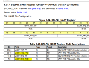
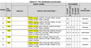
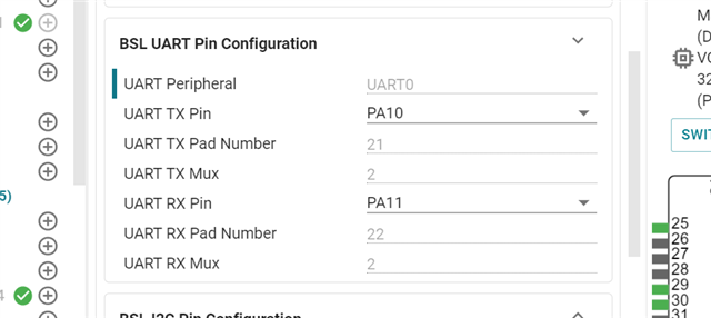
I want to use UART0 as BSL UART. Below is the pin mux of UART0:
But why the pin number in BSL tab is 21 and 22? Is it correct?
Thanks.
Best Regards,
Justin
Hi Justin,
The Pad refers to the value of the PINCMx which is in the BSLPIN_UART register
See below from the datasheet
and below from the TRM
The default BSL UART pins are already PA10 and PA11 so unless you are wanting to implement the secondary BSL, you shouldn't need to touch the non-main module.
Regards,
Luke
Hi Justin,
Yes, it should be possible. However, don’t forget to change the pins to match UART1, as in the picture below.
Best Regards,
Diego Abad
Hi Diego,
Thanks.
Do you have a BSL example in SDK?
I'm designing a demo board for customer projecct. It's better to confirm BSL function or the board cannot work.
Thanks.
Best Regards,
Justin
Hi Justin,
We have BSL examples in the SDK for the MSPM0G3507, but it should be easy to follow the same structure of the code on the MSPM0G1107. Those examples are in the following path of the Resource Explorer:
Arm®-based microcontrollers/Embedded Software/MSPM0 SDK (1.10.00.05)/Examples/ Development Tools/LP-MSPM0G3507LaunchPad/ Bootloader (BSL)
You should see three projects you can use as a reference.
Best Regards,
Diego Abad