Part Number: AM2634-Q1
Other Parts Discussed in Thread: SYSCONFIG, ASH
Hi Team,
I have some confusions related to the mapping of the GPIO modules and groups. Based on the references from the RM here is my understanding.
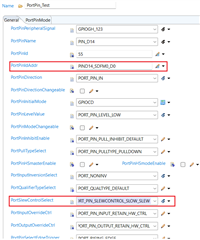
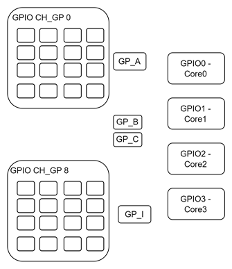
- There are 144 GPIO port pins available for IO processing. Each are interrupt capable
- These 144 pins are grouped into 9 groups (A-I) as in the MCAL Port config. These groups are also referred to as Banks in the RM.
- There are 4 GPIO modules GPIO0 - GPIO3
- Each of the modules are mapped to the corresponding cores Core 0 - Core3
- Each GPIO modules have configurations registers related to all 144 pins, as grouped in banks
Queries:
- Are there 144 (pins) * 4 (GPIO modules) = 576 pin configurations possible?
- Which pins/groups/banks are mapped to which core?
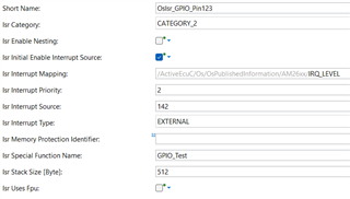
- There are 2 concepts for INT routing related to the GPIO pints
- GPIO_XBAR_INTRTR0 (Interrupt Router)
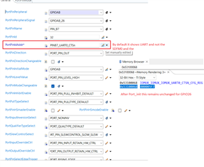
- INPUTXBAR (configuration seen in MCU Autosar module)
- Which of the above 2 concepts needs to be used to handle GPI input interrupt in specific port pins.
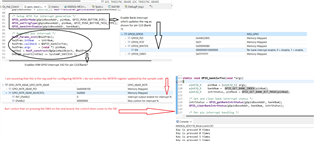
- Would need some clarification on the usage of bank interrupts as we notice that each core can handle only 4 GPIO interrupts (142 - 145) in the VIM related to that core.