Part Number: TMDSCNCD263
Other Parts Discussed in Thread: TMDSHSECDOCK, LP-CC2652RB, SYSCONFIG
Subject: UART Connection Issue with AM2634C and CC2652
Dear Texas Instruments Support,
I am currently working on a project that involves establishing a UART connection between the AM2634C and the CC2652, as well as between the AM2634C and Putty software running on a PC connected to the board via USB.
The AM2634C device I am using is connected to the TMDSHSECDOCK dock station, and I'm also working with an LP-CC2652RB module, which contains a CC2652 chip.
For the AM2634C, I've used the "mcu_plus_sdk_am263x_08_06_00_34" SDK, and for the CC2652, I've utilized the "simplelink_wbms_sdk_2_00_02_23_eng" SDK.
I am encountering some problems when trying to establish a UART connection between the AM2634C and the CC2652. Specifically, I've managed to declare a new UART interface in the sysconfig of the uart echo project (that works perfectly) and chosen available GPIO pins for mapping. For instance, ports L3 and M3 on the Sitara processor are mapped to pins 161 and 162 on the dock.
I modified the UART echo project from the "mcu_plus_sdk_am263x_08_06_00_34" SDK by replacing all instances of UART_CONSOLE with my new UART interface. Then, I connected pins 161 and 162 of the TMDSHSECDOCK with the Rx and Tx pins of the TM4C129, expecting at first for testing to send characters via the TM4C129 and get them back.
However, I'm currently experiencing inconsistent results. Most of the time, I am only able to receive characters from the AM with the TM4C, but not in reverse. On rare occasions, the setup works, but then if I flash the same code again it fails.
I put the protocol of the simpliest demonstration of my problem at the end of my request.
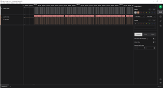
I have tested with an osciloscope and the TM4C129 correctly sends characters via UART (I also tested with a secound TM4C129 and together they exchange information well).
I'm not sure what could be causing this inconsistency, and I would greatly appreciate any guidance or support you could provide to help me troubleshoot this issue.
Thank you for your time and assistance.
Best Regards,
Théo Geairain

Procedure of the UART TEST
I- UART0 test
Create a new workspace.
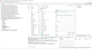
Import the uart_echo_am263x-cc_r5fss0-0_freertos_ti-arm-clang project from the mcu_plus_sdk_am263x_08_06_00_34.
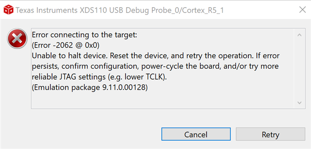
Flash the device (deselect the M4 processor).
Select the S26A0200 debugger.
Test UART 0.
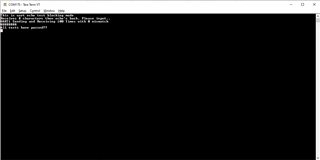
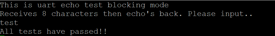
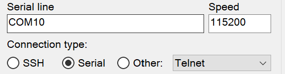
Open the serial port in a terminal and type characters (8), which are sent via UART 0 to the Sitara. Then they are returned to us and displayed in the serial port terminal.
UART 0 test validated.
Now we change the buffer size of APP_UART_RECEIVE_BUFSIZE to (1U) in uart_echo.c.
We add an infinite loop around the block "{ /* Read 8 chars */ and /* Echo chars entered */}".
Refash the device.
Now it sends back characters to us indefinitely, one by one.
II- Test UART 1.
1) Sitara Tx.
Open the sysconfig.
Add a UART interface.
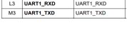
Rename it to CONFIG_UART1 and set the Rx on L3 and Tx on M3.
Now we duplicate all the UART_write lines, replacing CONFIG_UART_CONSOLE with CONFIG_UART1.
transferOK = UART_write(gUartHandle[CONFIG_UART1], &trans);
Flash the device again.
Next, we cross connect the Rx and Tx pins of the TM4C129 and the Sitara (pin 161 and 162).
Open the serial port of the TM4C129 in a terminal and send characters into the serial port of the Sitara. These are then returned to the TM4C129's serial port.
UART1 Tx test validated.
2) Sitara Rx.
After this, we change the UART_read lines by putting CONFIG_UART1. We thus expect to be able to send the characters in the TM4C129's serial port console and they will be read by the Sitara in UART 1.
When we test, it does not work.
UART1 Rx test not validated.