This thread has been locked.

If you have a related question, please click the "Ask a related question" button in the top right corner. The newly created question will be automatically linked to this question.

TM4C1294NCPDT: RTOS I2C driver: Need to use a different I2C bus (other than defined in enum)

Part Number: TM4C1294NCPDT
Other Parts Discussed in Thread: TMP006, TCA9555, TM4C1292NCPDT, EK-TM4C1294XL,

Hello,

I've a working reference code for my project in which 3 different I2C buses were used for the working project, i.e. I2C1, I2C2, I2C9 buses that are defined in the enum as below:

typedef enum EK_TM4C1294XL_I2CName {
    EK_TM4C1294XL_I2C1 = 0,
    EK_TM4C1294XL_I2C2,
	EK_TM4C1294XL_I2C9,

    EK_TM4C1294XL_I2CCOUNT
} EK_TM4C1294XL_I2CName;

But if I want to use an additional I2C bus i.e. I2C5 without interfering with the existing I2C communication (i.e., I2C1, 2 and 9) how do I do that? It is not defined in the enum.

The usage in RTOS is as below:

 stI2cConfig.vui8I2cBus = Board_I2C9;

where 

#define Board_I2C1 EK_TM4C1294XL_I2C1
#define Board_I2C2 EK_TM4C1294XL_I2C2
#define Board_I2C9 EK_TM4C1294XL_I2C9

The above are defined in Board.h file whereas I2C5 bus is not defined.

Please help in implementing I2C5 communication.

Best Regards,

Kiran

  • Hi ,

    Another similar question is the command to enable or disable the interrupt. Like in the current working project,the command to clear,disable and enable the interrupt in already defined pin is:

     GPIO_disableInt(BOARD_PORTF_PIN0);
     GPIO_clearInt(BOARD_PORTF_PIN0);
     GPIO_enableInt(BOARD_PORTF_PIN0);

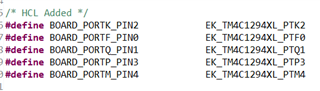
    where Pin PF0 is defined in Board.h as BOARD_PORTF_PIN0. But if we want to use additional pins for interrupt which are not defined in Board.h, for e.g. I need to use the pins PQ1, PP3 and PM4 pins in 3 different interrupt handlers and I want to clear, disable and enable the interrupts on these pins in their respective interrupt handlers similar to the above code snippet for pre-defined pin, what command should I use for similar purpose for those pins that are not pre-defined?

    Best Regards,

    Kiran

  • HI,

      You will need to add I2C5 to EK_TM4C1294XL_I2CName. Please refer to TI-RTOS user's guide section 5.2.2 for details. https://www.ti.com/lit/pdf/spruhd4

      Please also take a look a the TI-RTOS I2C TMP006 example. In this example, it uses I2C7 and I28 only. By comparing this example with your current code, you will get an idea where and how to add another I2C object. 

    where Pin PF0 is defined in Board.h as BOARD_PORTF_PIN0. But if we want to use additional pins for interrupt which are not defined in Board.h,

    Please also refer to the user's guide and also GPIO example. 

  • Hi Charles,

    Thanks for your reply.

    I tried implementing the way it is given in example code, but I've an issue that with TCA9555 IO Expander IC, I've first 12 bits declared as inputs and I'm expecting interrupt signal in the microcontroller but the IC is not generating the interrupt signal.

    The following is the initalisation code snippet for TCA9555 IC,with

    #define DI_SLAVEADDRESS2          0x26

        stI2cConfig.ui8regaddr = 0x06;
        stI2cConfig.vui8slaveAddress =  DI_SLAVEADDRESS2;
        stI2cConfig.vui8I2cBus = Board_I2C9;
        aui8txBuffer[0] = 0x06;
        aui8txBuffer[1] = 0xFF;
        aui8txBuffer[2] = 0x0F;
        stI2cConfig.pui8txbuffer = aui8txBuffer;
        stI2cConfig.pui8RxBuffer = aui8rxBuffer;
        stI2cConfig.vui8writeCount = 3;
        stI2cConfig.vui8readCount = 0;
        ioc_DII2CTransfer(&stI2cConfig);
    
        /* Writing Source Sink Configuration to output registers port1 */
        stI2cConfig.ui8regaddr = 0x03;
        stI2cConfig.vui8slaveAddress =  DI_SLAVEADDRESS2;
        stI2cConfig.vui8I2cBus = Board_I2C9;
        aui8txBuffer[0] = 0x03;
        aui8txBuffer[1] = ~((Source_Sink_Sel2 << 2) | (Source_Sink_Sel2 << 3)| (Source_Sink_Sel2 << 4)| (Source_Sink_Sel2 << 5)) & 0xF0;
    
        stI2cConfig.pui8txbuffer = aui8txBuffer;
        stI2cConfig.pui8RxBuffer = aui8rxBuffer;
        stI2cConfig.vui8writeCount = 2;
        stI2cConfig.vui8readCount = 0;
        ioc_DII2CTransfer(&stI2cConfig);
    

    Following is the schematic

    The 2 I2C signals (SDA and SCL) are pulled up at the microcontroller side.

    Could you please suggest why is the IC not generating the interrupt on applying input?

    Thanks,

    Kiran

  • I've first 12 bits declared as inputs

    What is 12bits mean?

    I'm expecting interrupt signal in the microcontroller but the IC is not generating the interrupt signal.

    In TI-RTOS, the interrupt is managed bu Hwi. Did you enable interrupt through Hwi? Please refer to this post where the TI-RTOS training material is provide. Particularly look for the Hwi chapter. 

    https://e2e.ti.com/support/processors-group/processors/f/processors-forum/887582/faq-where-is-the-old-ti-rtos-workshop/3281791#3281791

    Also refer to I2C driver user's guide https://www.ti.com/lit/pdf/spruhd4.

    A heads-up, I will be on vacation starting tomorrow for the rest of week. my response will be extremely delayed. 

  • Hi Charles,

    Thanks for your response.

    In TI-RTOS, the interrupt is managed bu Hwi. Did you enable interrupt through Hwi? Please refer to this post where the TI-RTOS training material is provide. Particularly look for the Hwi chapter.

    Yes, I enabled the interrupts in my project's .cfg file. See screenshot below.

    In our schematic, we have 2 IO expander ICs (TCA9555) connected to same I2C lines but different addresses.

    The interrupt line 1 (INT1_N) is connected to PF0 pin of microcontroller (vector number 46) and the interrupt line 2 (INT2_N) is connected to PQ1 pin of microcontroller (vector number 101)

    The initialization code of both the IO expander ICs are given below.

            stI2cConfig.ui8regaddr = 0x06;
            stI2cConfig.vui8slaveAddress =  DI_SLAVEADDRESS1;
            stI2cConfig.vui8I2cBus = Board_I2C9;
            aui8txBuffer[0] = 0x06;
            aui8txBuffer[1] = 0xFF;
            aui8txBuffer[2] = 0x0F;
            stI2cConfig.pui8txbuffer = aui8txBuffer;
            stI2cConfig.pui8RxBuffer = aui8rxBuffer;
            stI2cConfig.vui8writeCount = 3;
            stI2cConfig.vui8readCount = 0;
            ioc_DII2CTransfer(&stI2cConfig);

            stI2cConfig.ui8regaddr = 0x06;
            stI2cConfig.vui8slaveAddress =  DI_SLAVEADDRESS2;
            stI2cConfig.vui8I2cBus = Board_I2C9;
            aui8txBuffer[0] = 0x06;
            aui8txBuffer[1] = 0xFF;
            aui8txBuffer[2] = 0x0F;
            stI2cConfig.pui8txbuffer = aui8txBuffer;
            stI2cConfig.pui8RxBuffer = aui8rxBuffer;
            stI2cConfig.vui8writeCount = 3;
            stI2cConfig.vui8readCount = 0;
            ioc_DII2CTransfer(&stI2cConfig);

    where 

    #define DI_SLAVEADDRESS1 0x27
    #define DI_SLAVEADDRESS2 0x26

    I'm getting interrupt pulse at INT1_N but not at INT2_N if I apply input (PO0 to PO7 lines) on the IO expander. Is it due to the same I2C lines(I2C9) or any other issue?

    Please guide.

    Best Regards,

    Kiran

  • Hi,

      I'm currently on vacation for the rest of the week. Please expect delay in my response. I also have no access to my PC so can't really check your terminal connections against the datasheet. 

      You said the INT2 is connected to PQ1. Why are you applying your interrupt pulse to PO0-PO7? 

      Can you repeat the same problem on the Launchpad? 

      Can you try a simple experiment to only generate interrupt on PQ1. There is  a TI-RTOS GPIO interrupt that you can reference. 

  • Hi Charles,

    I'm getting the INT2_N pulse on the second IO expander. It wasn't coming on the output side of the isolator that we were using, we selected a wrong isolator.

    You said the INT2 is connected to PQ1. Why are you applying your interrupt pulse to PO0-PO7?

    I'm not applying the interrupt pulse to PO0-PO7, but to the GPIO PQ1 of microcontroller.

    Although now the second interrupt pulse is going to the microcontroller. But it's not going in the second interrupt handler in my code

    Please see the second interrupt pulse below.

    I've posted the interrupt activation code, schematic and interrupt handler code snippet in my previous post. It is set for low level trigger in the main.c file

    #ifdef DI_ISR_I2C_READ
        /* Digital input interrupt is set for Low level trigger */
        GPIOIntTypeSet(GPIO_PORTF_BASE, BOARD_PORTF_PIN0, GPIO_LOW_LEVEL);
        GPIOIntTypeSet(GPIO_PORTQ_BASE, BOARD_PORTQ_PIN1, GPIO_LOW_LEVEL);
        
    #endif
    

    Could you tell me if I'm doing any mistake in the activation of interrupt handler? Or why the interrupt pulse of second IO expander is not entering in the second interrupt handler, whereas it's working fine in case of first interrupt handler?

    Best Regards,

    Kiran

  • Hi,

    Adding to the above, please see the schematic screenshot for INT2_N output pin of second IO expander to the GPIO PQ1 pin of microcontroller (pulled up by 10k to 3.3V)

    I'm getting interrupt pulse at INT1_N but not at INT2_N if I apply input (PO0 to PO7 lines) on the IO expander.

    I'm applying an input voltage to any of the PO0-PO7 input lines of the second IO expander to get an output INT2_N pulse from the IO expander going into the GPIO PQ1 pin of microcontroller to be handled in an interrupt handler.

    Best Regards,

    Kiran

  • Also,

    I've defined the GPIO PQ1 in tm4c1292ncpdt.c file as below

    Please help if  I am missing anything.

    Best Regards,

    Kiran

  • Hi Kiran,

      Reading the TI-RTOS gpiointerrupt example source code for the EK_TM4C1294XL.c file,  it has the below comments highlighted in red. I wanted to make sure if you obey the ordering requirement as specified in the comment. Please see below code snippet. As you can see for this example, there are two interrupt input pins and two GPIO output pins. The order is PJ0 followed by PD0. This must match the order defined in EK_TM4C1294XL.h. Please also make sure your EK_TM4C1294XL.h.is updated for the EK_TM4C1294XL_GPIOName structure according to your application. 

    Code snippet from EK_TM4C1294XL.c. 

    /*
    * Array of Pin configurations
    * NOTE: The order of the pin configurations must coincide with what was
    * defined in EK_TM4C1294XL.h
    * NOTE: Pins not used for interrupts should be placed at the end of the
    * array. Callback entries can be omitted from callbacks array to
    * reduce memory usage.
    */
    GPIO_PinConfig gpioPinConfigs[] = {
    /* Input pins */
    /* EK_TM4C1294XL_USR_SW1 */
    GPIOTiva_PJ_0 | GPIO_CFG_IN_PU | GPIO_CFG_IN_INT_RISING,
    /* EK_TM4C1294XL_USR_SW2 */
    GPIOTiva_PD_0 | GPIO_CFG_IN_PU | GPIO_CFG_IN_INT_RISING,

    /* Output pins */
    /* EK_TM4C1294XL_USR_D1 */
    GPIOTiva_PN_1 | GPIO_CFG_OUT_STD | GPIO_CFG_OUT_STR_HIGH | GPIO_CFG_OUT_LOW,
    /* EK_TM4C1294XL_USR_D2 */
    GPIOTiva_PN_0 | GPIO_CFG_OUT_STD | GPIO_CFG_OUT_STR_HIGH | GPIO_CFG_OUT_LOW,
    };

    Code snippet from EK_TM4C1294XL.h.

    /*!
    * @def EK_TM4C1294XL_GPIOName
     * @brief Enum of LED names on the EK_TM4C1294XL dev board
    */
    typedef enum EK_TM4C1294XL_GPIOName {
    EK_TM4C1294XL_USR_SW1 = 0,
    EK_TM4C1294XL_USR_SW2,
    EK_TM4C1294XL_D1,
    EK_TM4C1294XL_D2,

    EK_TM4C1294XL_GPIOCOUNT
    } EK_TM4C1294XL_GPIOName;

    I will suggest you modify the TI-RTOS gpiointerrupt example to use PQ1 as an interrupt input. Can you get it to work?

  • Hi Charles,

    The pins are defined in the correct order. Screenshot below is from tm4c1292ncpdt.c

    The following is from tm4c1292ncpdt.h

    Following is from Board.h

    The interrupt example I can find is from the path:

    C:\ti\tirtos_tivac_2_16_01_14\products\TivaWare_C_Series-2.1.4.178\examples\boards\ek-tm4c1294xl\interrupts

    But this example has interrupt number being given in the startup_ccs.c file but in my project .cfg file is used for the same.

    Regarding the example given in the path,C:\ti\tirtos_tivac_2_16_01_14\tirtos_tivac_2_16_01_14_examples\TI\EK_TM4C1294XL\gpiointerrupt

    I dont find any project file,it is only .c and .h files

    Can you give the path of the gpiointerrupt working project that you're referring to?

    Thanks,

    Kiran 

  • Hi Kiran,

      You have PJ0, PJ1, JK2, JF0, PQ1, PP3 and PM4. Is PQ1 the only pin that does not generate interrupt? Do you have any interrupt problem with the rest of pins for PJ0, JK2, JF0, PQ1, PP3 and PM4?

    Regarding the example given in the path,C:\ti\tirtos_tivac_2_16_01_14\tirtos_tivac_2_16_01_14_examples\TI\EK_TM4C1294XL\gpiointerrupt

    I dont find any project file,it is only .c and .h files

    Can you give the path of the gpiointerrupt working project that you're referring to?

    You can use Resource Explorer from within CCS to import the various TI-RTOS examples? I would strongly you play with this example first and get it to work. You can then modify it for PQ1 interrupt generation. Don't add other pins yet until you can get PQ1 to work. After you get PQ1 to work by modifying the example, you can gradually add other pins per your application requirements. 


  • Hi Charles,

    You have PJ0, PJ1, JK2, JF0, PQ1, PP3 and PM4. Is PQ1 the only pin that does not generate interrupt? Do you have any interrupt problem with the rest of pins for PJ0, JK2, JF0, PQ1, PP3 and PM4?

    The interrupt is currently working only on PF0 pin, not on other pins. I'm trying to add additional pin PQ1 for additional interrupt.

    You can use Resource Explorer from within CCS to import the various TI-RTOS examples? I would strongly you play with this example first and get it to work. You can then modify it for PQ1 interrupt generation. Don't add other pins yet until you can get PQ1 to work. After you get PQ1 to work by modifying the example, you can gradually add other pins per your application requirements. 

    Regarding Resource Explorer, I'm currently using CCS v7.4 version as my project is currently working on this version and Resource explorer doesn't open in that version.

    Best Regards,

    Kiran

  • Regarding Resource Explorer, I'm currently using CCS v7.4 version as my project is currently working on this version and Resource explorer doesn't open in that version.

    7.4 is very old. In any case, don't you see View -> Resource Explorer Offline?

  • Hi Charles,

    I went in the path from the above tab View -> Resource Explorer Classic then following opened:

    It's not showing the GPIO Interrupt project, just the steps to import and build the project.

    Please help.

    Best Regards,

    Kiran

  • Hi Charles,

    So I'm trying the example in another system with latest CCS version CCS12.1 version

    I did the changes in EK_TM4C1294NCPDT.c file in gpioPinConfigs[] array as below:

    GPIO_PinConfig gpioPinConfigs[] = {
        /* Input pins */
        /* EK_TM4C1294XL_PQ1 */
        GPIOTiva_PQ_1 | GPIO_CFG_IN_PU | GPIO_CFG_IN_INT_RISING,
        /* EK_TM4C1294XL_USR_SW2 */
        GPIOTiva_PJ_1 | GPIO_CFG_IN_PU | GPIO_CFG_IN_INT_RISING,
    
        /* Output pins */
        /* EK_TM4C1294XL_USR_D1 */
        GPIOTiva_PN_1 | GPIO_CFG_OUT_STD | GPIO_CFG_OUT_STR_HIGH | GPIO_CFG_OUT_LOW,
        /* EK_TM4C1294XL_USR_D2 */
        GPIOTiva_PN_0 | GPIO_CFG_OUT_STD | GPIO_CFG_OUT_STR_HIGH | GPIO_CFG_OUT_LOW,
    };

    I replaced the first GPIO in the example,i.e. PJ0 with PQ1. Defined the same in Board.h as 

    Also in the file EK_TM4C1294NCPDT.h file :

    Also, in gpiointerrupt.c file the following changes were done to replace USR_SW1 (BOARD_BUTTON0) with Board_PQ1.

    But after compiling and programming the TI Launchpad with the respective bin file,it is still toggling the LED with USR_SW1 as in the example and not through PQ1.

    Also, in my project I'm enabling the interrupt in the .cfg file and not in the .c file

    Please guide how to enable PQ1 for interrupt.

    Best Regards,

    Kiran

  • Hi Kiran,

      Can you check the NVIC register if PQ is enabled. If you run the stock example, there are three interrupt channels enabled at NVIC and they are PD, PJ and Timer1. If you change to PQ1 then I expect interrupt channel 84 (if you enable the entire Port Q) or 85 (if you enable PQ1 specifically) is enabled. 

    Below is from the device datasheet. 

  • Hi Charles,

    How do I check these registers? If I run this example in the Debug mode then interrupt won't come as it's run time. Please see below

    Please guide.

    Best Regards,

    Kiran

  • Hi Kiran,

      I just wanted to check if the interrupt for PQ port is enabled. Your current NVIC has all interrupt channels disabled. Your screenshot is probably taken before the code is run. You can put a breakpoint or single step the call to GPIO_enableInt(Board_PQ1). See if any bits of NVIC_ENx is set. Run the stock example and compare the NVIC settings with your modified code. 

  • Hi Charles,

    You can put a breakpoint or single step the call to GPIO_enableInt(Board_PQ1).

    Added the breakpoint as you mentioned. See below:

    Please advise next steps for my original code.

    Thanks,

    Kiran 

  • Hi Kiran,

     Reading your screenshot, I do see channel 85 (Port Q1) enabled as well as channel 51 (Port J). The timer1A which is used by the OS is not enabled perhaps because the BIOS_Start() is not yet called. 

    Can you show the register settings for GPIO_PORTQ? Let's make sure the interrupt is also enabled for PortQ at the module level. 

    Please bear in mind that you have configured PortQ1 for interrupt on rising edge. What is your input to PQ1? Can you verify that you created a rising edge to cause an interrupt?

     Can you put a breakpoint on the entry to both gpioButtonFxn0() and gpioButtonFxn1(). I want to also verify if a wrong callback is called due to ordering of the GPIO structure. 

  • Hi Charles,

    The interrupt handler is working in the example now and also in my working project I've 2 interrupt handlers (corresponding to 2 IO expanders) which are also working.

    In my schematic, I've 2 IO expanders,TCA9555 for digital inputs (0-11) and digital inputs (12-23) respectively causing interrupt 1st and 2nd and 2 other IO expanders for corresponding LEDs (0-11) and LEDs (12-23) respective to the digital input being applied.

    The I2C line for digital input IO expanders is I2C9 (with different addresses 0x27 and 0x26) and that of the 2 LED IO expanders is I2C2 (with different addresses 0x27 and 0x26).

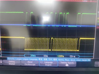
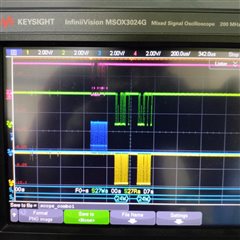
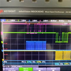
    Following are my observations (scope captures) for I2C signals to Digital Input IO Expander 1 (and 2) vs LED IO Expander 1 (and 2) in 2 different interrupt handlers:

    Details of signals and their respective colours In scope capture:

    • Yellow : LED SCL
    • Green : LED SDA
    • Blue : DI SCL
    • Pink : DI SDA

    Case 1:

    ISR 1 (0-11 DI) : Both sets glow

    • Set 1: 0-11 LEDs
    • Set 2: 12-23LEDs


    In 1st IO expander's Interrupt handler, i.e. ISR1, I'm giving I2C command to both of the IO Expanders glowing LEDs (0-11) and LEDs (12-23) and they're all glowing

    Case 2: 

    ISR 2 (12-23 DI) : Both sets glow

    • Set 1: 0-11 LEDs
    • Set 2: 12-23 LEDs

    In 2nd IO expander's Interrupt handler, i.e. ISR2, I'm giving I2C command to both of the IO Expanders glowing LEDs (0-11) and LEDs (12-23) and they all glow.

    Case 3:

    ISR 1 (0-11 DI) : Set  2 doesn’t glow

    • Set 2: 12-23 LEDs


    ISR 2(12-23 DI) : Set 1 glows

    • Set 1: 0-11 LEDs

    Case 4 :

    ISR 1 (0-11 DI) : Set 1 glows

    • Set 1: 0-11 LEDs

    ISR 2 (12-23 DI): Doesn’t glow

    • Set 2: 12-23 LEDs

    In case 3 and 4,it is observed that the second LED IO expander doesn't work properly (12-23LEDs) when run individually from any one interrupt handler.

    The 2 IO expanders for LEDs have 0x27 and 0x26 addresses. The code for driving the 2 LEDs 

    #ifdef USE_DI
        i2cConfigbus stI2cConfig;
        uint8_t aui8TxBuffer[4];
        uint8_t aui8RxBuffer[3];
    
        /* Configuration of Digital Input LED*/
        IOC_DEBUG_DRIVER("\nDigital Input LED Update\n");
        IOC_DEBUG_DRIVER_FLUSH();
    
        aui8TxBuffer[0] = DIO_OUTPUTREG_PORTTWO;
        stI2cConfig.ui8regaddr = DIO_OUTPUTREG_PORTTWO;
        stI2cConfig.vui8slaveAddress =  DI_LED_SLAVEADDRESS;
        stI2cConfig.vui8I2cBus = Board_I2C2;
        stI2cConfig.pui8txbuffer = aui8TxBuffer;
        stI2cConfig.pui8RxBuffer = aui8RxBuffer;
        stI2cConfig.vui8writeCount = 1;
        stI2cConfig.vui8readCount = 1;
        ioc_DigitalLEDI2CTransfer(&stI2cConfig);
    
        aui8TxBuffer[2] = (*((uint8_t*)stI2cConfig.pui8RxBuffer+0)) & 0xF0;
    
        channelStatus = ~channelStatus;
    
        aui8TxBuffer[1] = channelStatus & 0xFF;
        aui8TxBuffer[2] = aui8TxBuffer[2] | ((channelStatus >> 8) & 0x0F);
    
        aui8TxBuffer[0] = DIO_OUTPUTREG_PORTONE;
        stI2cConfig.ui8regaddr = DIO_OUTPUTREG_PORTONE;
        stI2cConfig.vui8slaveAddress =  DI_LED_SLAVEADDRESS;
        stI2cConfig.vui8I2cBus = Board_I2C2;
        stI2cConfig.pui8txbuffer = aui8TxBuffer;
        stI2cConfig.pui8RxBuffer = aui8RxBuffer;
        stI2cConfig.vui8writeCount = 3;
        stI2cConfig.vui8readCount = 0;
        ioc_DigitalLEDI2CTransfer(&stI2cConfig);
    

    i2cConfigbus stI2cConfig;
        uint8_t aui8TxBuffer[4];
        uint8_t aui8RxBuffer[3];
    
        /* Configuration of Digital Input LED*/
        IOC_DEBUG_DRIVER("\nDigital Input LED Update\n");
        IOC_DEBUG_DRIVER_FLUSH();
    
        aui8TxBuffer[0] = DIO_OUTPUTREG_PORTTWO;
        stI2cConfig.ui8regaddr = DIO_OUTPUTREG_PORTTWO;
        stI2cConfig.vui8slaveAddress =  DI_LED_SLAVEADDRESS2;
        stI2cConfig.vui8I2cBus = Board_I2C2;
        stI2cConfig.pui8txbuffer = aui8TxBuffer;
        stI2cConfig.pui8RxBuffer = aui8RxBuffer;
        stI2cConfig.vui8writeCount = 1;
        stI2cConfig.vui8readCount = 1;
        ioc_DigitalLEDI2CTransfer(&stI2cConfig);
    
        aui8TxBuffer[2] = (*((uint8_t*)stI2cConfig.pui8RxBuffer+0)) & 0xF0;
    
        channelStatus = ~channelStatus;
    
        aui8TxBuffer[1] = channelStatus & 0xFF;
        aui8TxBuffer[2] = aui8TxBuffer[2] | ((channelStatus >> 8) & 0x0F);
    
        aui8TxBuffer[0] = DIO_OUTPUTREG_PORTONE;
        stI2cConfig.ui8regaddr = DIO_OUTPUTREG_PORTONE;
        stI2cConfig.vui8slaveAddress =  DI_LED_SLAVEADDRESS2;
        stI2cConfig.vui8I2cBus = Board_I2C2;
        stI2cConfig.pui8txbuffer = aui8TxBuffer;
        stI2cConfig.pui8RxBuffer = aui8RxBuffer;
        stI2cConfig.vui8writeCount = 3;
        stI2cConfig.vui8readCount = 0;
        ioc_DigitalLEDI2CTransfer(&stI2cConfig);
    

    where

    #define DI_LED_SLAVEADDRESS 0x27
    #define DI_LED_SLAVEADDRESS2 0x26

    Is there anything wrong in the code for driving the second set of LEDs?

    Best Regards,

    Kiran

  • The interrupt handler is working in the example now and also in my working project I've 2 interrupt handlers (corresponding to 2 IO expanders) which are also working.

    Hi Kiran,

      Perhaps you can explain why it is working now since we have spent a lot of time debugging the problem. What did you change to make it work?

    In my schematic, I've 2 IO expanders,TCA9555 for digital inputs (0-11) and digital inputs (12-23) respectively causing interrupt 1st and 2nd and 2 other IO expanders for corresponding LEDs (0-11) and LEDs (12-23) respective to the digital input being applied.

    The I2C line for digital input IO expanders is I2C9 (with different addresses 0x27 and 0x26) and that of the 2 LED IO expanders is I2C2 (with different addresses 0x27 and 0x26).

    I'm still not very clear with your systems. I have some questions.

     - How many IO expander (TCA9555) do you have on your design? Is it two or four? It seems to me you use I2C9 to interface with two DI IO expanders and I2C2 to interface with another two IO expanders for LEDs. 

     - For I2C9 that is used to interface with the two DI IO expanders, there are two interrupts connected to PF0 and PQ1. Is this correct?

     - For I2C2 that is used to interface with the two LED IO expanders, what are the interrupt channels you used? Which GPIO inputs are the two LED IO expander interrupts connected to?

      - For the two DI IO expanders you configure the IOs as input, correct?

      - For the two LED IO expanders you configure the IOs as output, correct? This one I'm not very clear as to how you are connecting the LEDs to TCA9555.

    Following are my observations (scope captures) for I2C signals to Digital Input IO Expander 1 (and 2) vs LED IO Expander 1 (and 2) in 2 different interrupt handlers:

    Do you have a total of two interrupt handlers or four interrupt handlers? I know at least you have two for PF0 and PQ1. I'm not sure about the LED IO expanders. Please clarify. 

    In case 3 and 4,it is observed that the second LED IO expander doesn't work properly (12-23LEDs) when run individually from any one interrupt handler.

    In case 1 and 2, you can glow the second LED expander (12-23), this means that you are giving the correct address (0x26). I don't know why it is not working in case 3 and 4. Can you temporarily remove the first LED expander from the bus? Need to know if there is some type of conflict on the bus since the two LED expanders share the same bus. It will be easier for you to debug too. 

  • Hi Charles,

    Perhaps you can explain why it is working now since we have spent a lot of time debugging the problem. What did you change to make it work?

    I wasn't enabling the interrupt at the trigger point

    How many IO expander (TCA9555) do you have on your design? Is it two or four? It seems to me you use I2C9 to interface with two DI IO expanders and I2C2 to interface with another two IO expanders for LEDs. 

    Yes, you understood it right

     - For I2C9 that is used to interface with the two DI IO expanders, there are two interrupts connected to PF0 and PQ1. Is this correct?

    Yes

     - For I2C2 that is used to interface with the two LED IO expanders, what are the interrupt channels you used? Which GPIO inputs are the two LED IO expander interrupts connected to?

    Since the two LED IO expanders are only driving the outputs (from the PF0,PQ1 ISRs) and there's no input on them so interrupts are not being taken care of in this case.

    - For the two DI IO expanders you configure the IOs as input, correct?

    Yes

    - For the two LED IO expanders you configure the IOs as output, correct? This one I'm not very clear as to how you are connecting the LEDs to TCA9555.

    Yes IOs are configured as outputs. Please see the schematic screenshot


    Do you have a total of two interrupt handlers or four interrupt handlers? I know at least you have two for PF0 and PQ1. I'm not sure about the LED IO expanders. Please clarify

    There are only 2 interrupt handlers for PF0 AND PQ1 and not for LED IO expanders

    In case 1 and 2, you can glow the second LED expander (12-23), this means that you are giving the correct address (0x26). I don't know why it is not working in case 3 and 4. Can you temporarily remove the first LED expander from the bus? Need to know if there is some type of conflict on the bus since the two LED expanders share the same bus. It will be easier for you to debug too. 

    When both :LED IO expanders are being turned on from a single interrupt handler together at the same time (either ISR1 or ISR2) then all LEDs get turned on but when it's one LED IO expander through one ISR each then the second set (12-23 LEDs) doesn't work. I'll try to do the experiment.

    If there's any other suggestion based on above observation then please let me know.

    Thanks,

    Kiran

  • When both :LED IO expanders are being turned on from a single interrupt handler together at the same time (either ISR1 or ISR2) then all LEDs get turned on but when it's one LED IO expander through one ISR each then the second set (12-23 LEDs) doesn't work. I'll try to do the experiment.

    If there's any other suggestion based on above observation then please let me know.

    Let me know your experiment result.

    I will also suggest you zoom in to case 1 and 2 where you send the command to the 2nd IO expander and look at the data on SDA pin. Compare it with case 3 and 4. Is the data sent to the 2nd LED expander for case 3 and 4 the same as in case 1 and 2? Your screenshots are zoom-out shots which don't reveal the details. 

  • Hi Charles,

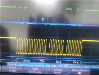
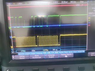
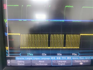
    Following are the zoom in captures of the scope for the 4 cases:

    Case 1:

    ISR1


    Case 2:

    ISR 2: 


    Case 3:

    ISR1:


    ISR2:


    Case 4:

    ISR1:


    ISR2:


    How do I remove I2C line from one LED IO expander? As it's assembled in the PCB,should I remove the first IO expander IC?

    Best Regards,

    Kiran
  • How do I remove I2C line from one LED IO expander? As it's assembled in the PCB,should I remove the first IO expander IC?

    I know it is much harder to alter the PCB than doing a software change. This is what I will recommend you do before you remove the first LED expander. 

      - Don't use ISR1 or ISR2 to write to the 2nd LED expander to turn on the LED. Simply use I2C2 to write the command directly to the 2nd LED expander n your main() or somewhere. Will you turn on the LED (13-24)?

     - Back to your original method. I suppose in your ISR1 or ISR2, you first send command to the first LED expander followed by the command to the 2nd LED expander, correct? Why don't you reverse the order? Try to send the command to the 2nd LED expander (13-24) first followed by the command to the 1st expander. Will you see different result?

      - If the software experiment does not work, then somehow remove the first LED expander from the bus. 

  • Hi Charles,

    Back to your original method. I suppose in your ISR1 or ISR2, you first send command to the first LED expander followed by the command to the 2nd LED expander, correct? Why don't you reverse the order? Try to send the command to the 2nd LED expander (13-24) first followed by the command to the 1st expander. Will you see different result?

    I already showed the result of this experiment, turning ON both LED expanders in same ISR turns all LEDs ON there's no issue in that.

    I will try the other things you suggested.

    I'm also trying the UART print method (in ISR ) to debug the issue with the command ioc_UartPrint("\nDig1 \n"); in ISR1

    And ioc_UartPrint("\n ISR2 \n"); in ISR2. And only 'Dig1' is being printed and in second interrupt handler, all the messages of initialization get printed again and system hangs, but when I comment it the system doesn't hang.

    void ioc_UartPrint( const char *fmt, ... )
    {
    	Semaphore_pend(Sem_Uart_Handle, BIOS_WAIT_FOREVER);
        uint32_t viIntValue;  /* Used to store any int arguments. */
        char cCharValue;
        uint32_t viStrLength;
        char *piStringTemp;
        char aicBuffer[20];
        va_list vaArgs;  /* Used as a pointer to the next variable argument. */
    
        va_start( vaArgs, fmt );  /* Initialize the pointer to arguments. */
    
        while (*fmt)
        {
            if ('%' == *fmt)
            {
                fmt++;
                switch (*fmt)
                {
                     case 'd':
                         viIntValue = va_arg( vaArgs, int);
                         ioc_Itoa(viIntValue, aicBuffer, 10);
                         viStrLength = strlen(aicBuffer);
                         UARTUtils_devicewrite(UART_DEIVCE, aicBuffer,
                                               viStrLength);
                         break;
    
                     case 'x':
                    	  viIntValue = va_arg( vaArgs, int);
                    	  ioc_Itoa(viIntValue, aicBuffer, 16);
                    	  viStrLength = strlen(aicBuffer);
                    	  UARTUtils_devicewrite(UART_DEIVCE, aicBuffer,
                    	                        viStrLength);
    					  break;
    
                     case 'c':
    					  cCharValue = va_arg( vaArgs, char);
    					  UARTUtils_devicewrite(UART_DEIVCE, &cCharValue, 1);
    					  break;
    
                     case 's':
                    	  piStringTemp = va_arg(vaArgs , char *);
                    	  viStrLength = strlen(piStringTemp);
                    	  UARTUtils_devicewrite(UART_DEIVCE, piStringTemp,
                    	                        viStrLength);
                    	  break;
    
                 }
            }
            else
               /* Not a format character, copy it to output. */
    
            UARTUtils_devicewrite(UART_DEIVCE, fmt, 1);
            fmt++;
        }
        va_end( vaArgs );
        Semaphore_post(Sem_Uart_Handle);
    }
    

    Can I debug with some other printf method?

    Best Regards,

    Kiran

  • I will never recommend inserting printf or UARTprintf type of logging in the ISR. You are in a real time operation. You are supposed to go in and out of Hwi/interrupt quickly. When you insert a C-style printf or a UARTprintf, you will stay inside the ISR as long as the UART is ongoing. Hwi/Interrupt has higher priority than any of your user tasks. The longer the message you want to print out the longer you stay in the ISR handler. This will starve other tasks from running. 

  • I already showed the result of this experiment, turning ON both LED expanders in same ISR turns all LEDs ON there's no issue in that.

    There is a difference. In your ISR, you must have sent a command to LED expander address 0x27 first and then another command to expander address 0x26, right? I'm saying to reverse the order. by sending a command to expander address 0x26 first followed by the command to expander address 0x27. Unless you have already done so. 

  • Hi Charles,

    We have 2 boards with same I2C lines (I2C2) driving 3 LED IO expanders (2 on one board and 1 on another board),so I tried to drive the only LED IO expander on the other board having only 1 IO expander (with address as 0x24) using third interrupt handler (with INT3 of third digital IO expander ).

    Following are the scope captures:


    But the LEDs don't glow.

    Can you guide where I'm wrong?

    Best Regards,

    Kiran

  • I think there is a glitch on your SDA. Although your writing to address 0x24, the slave may have interpreted the address byte for a different address and hence not react to it. What pullup resistor value do you use?

  • What pullup resistor value do you use?

    See below:

    Please advise if you have any comments.

    Thanks,

    Kiran

  • Never mind. Looking at the scope again, I don't think that glitch is on the address but on the 9th bit which is the ACK. Since the master is receiving the correct ACK from the slave, it should be no issue. 

    I don't know much about the TCA9555. What is the difference between the 3rd and fourth captures? 

    In 3rd capture I see 24Wa -> 03a -> S24Ra -> FFa.

    In 4th capture I see 24Wa -> 02a -> FFa -> FFa

    Looks like In capture 3, you are reading from register address 0x3 and you are reading back a value of 0xFF. In the capture 4, you are writing to register address 0x2 with values of 0xFF. What do these commands do to the IO expander? What is the expected returned value in capture 3 when you read from register 0x3?

  • Hi Charles,

    This is the code in the existing working project for driving LEDs(IO expander) based on the Channel Status of Digital Input Channels being applied on the DI IO expander. Following is the code snippet.

        aui8TxBuffer[0] = DIO_OUTPUTREG_PORTTWO;
        stI2cConfig.ui8regaddr = DIO_OUTPUTREG_PORTTWO;
        stI2cConfig.vui8slaveAddress =  DI_LED_SLAVEADDRESS;
        stI2cConfig.vui8I2cBus = Board_I2C2;
        stI2cConfig.pui8txbuffer = aui8TxBuffer;
        stI2cConfig.pui8RxBuffer = aui8RxBuffer;
        stI2cConfig.vui8writeCount = 1;
        stI2cConfig.vui8readCount = 1;
        ioc_DigitalLEDI2CTransfer(&stI2cConfig);
    
        aui8TxBuffer[2] = (*((uint8_t*)stI2cConfig.pui8RxBuffer+0)) & 0xF0;
    
        channelStatus = ~channelStatus;
    
        aui8TxBuffer[1] = channelStatus & 0xFF;
        aui8TxBuffer[2] = aui8TxBuffer[2] | ((channelStatus >> 8) & 0x0F);
    
        aui8TxBuffer[0] = DIO_OUTPUTREG_PORTONE;
        stI2cConfig.ui8regaddr = DIO_OUTPUTREG_PORTONE;
        stI2cConfig.vui8slaveAddress =  DI_LED_SLAVEADDRESS;
        stI2cConfig.vui8I2cBus = Board_I2C2;
        stI2cConfig.pui8txbuffer = aui8TxBuffer;
        stI2cConfig.pui8RxBuffer = aui8RxBuffer;
        stI2cConfig.vui8writeCount = 3;
        stI2cConfig.vui8readCount = 0;
        ioc_DigitalLEDI2CTransfer(&stI2cConfig);
    

    And it works in the existing working project with the same respective LED glowing as the channel number on which digital input is being applied on the other IO expander(corresponding to the digital inputs).

    Best Regards,

    Kiran

  • This is the code in the existing working project for driving LEDs(IO expander) based on the Channel Status of Digital Input Channels being applied on the DI IO expander. Following is the code snippet.

    I don't see a problem on your code if they already work for you on a different board. You haven't answered my questions. Are you seeing on the bus what you are intending to write and read? When you read back 0xFF, is that expected? When you write two 0xFF to register 0x2, is that what you are trying to write? If you believe you are writing the correct command to the TCA9555 and the bus confirms the correct waveforms then I will suggest you open a new thread with the part number TCA9555. Show in the new thread the command you send and the waveforms you capture. I hope experts supporting the TCA9555  can shed some lights on how to diagnose the problem. 

  • Hi Charles,

    I'm not sure about what is expected in the existing project. I think I need to go deeper in it to understand the values being read back.

    I've created a new post:

    (+) TCA9555: Interface forum - Interface forum - Interface - TI E2E support forums

    Please share your comments there also.

    Thanks,

    Kiran

  • I will suggest you update the new post and focus on what your current problem and be fair to the experts there so they do not need to read through several weeks of posts in this thread. There are issues that you resolve that has nothing to do with TCA955. For examples, we spent weeks to just resolve interrupt on PQ1. They do not need to read this. They will be lost and kick the thread if you ask them to read them. 

    As I mentioned, show your latest problem only. Show the command that you want to send to turn on the LED and the waveforms. If you believe the command is sent correctly and verified on the waveform, why don't the LED turn on?

  • Hi Charles,

    I've posted the details of my current issue in that post. Currently, I'm facing an issue that I'm only enabling the third interrupt handler (i.e., initialising only the third digital input IO expander and the third LED IO expander, removed the first two LED IO expanders from PCB). Not all LEDs glow in this case too, but few random LEDs from the set glow.

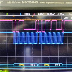
    But after applying the digital input on the third IO expander, the I2C clock line of digital input IO expander goes low. See scope capture below.

    In the above scope capture, the blue line is digital input I2C SCL and the pink line is digital input I2C SDA.

    The green and yellow are LED I2C SDA and SCL respectively.

    Can you suggest why this is going low? Maybe this is the reason for the LEDs not responding properly.

    Also, in TCA9555 interface forum they've written the following response.

    Is your I²C library able start more than a single I²C transaction? If not, then the second (and third) call to ioc_DigitalLEDI2CTransfer() aborts the previous one. (This has nothing to do with the TCA9555 itself and should be discussed in the TM4C forum.)

    Could you share your feedback on this?

    Thanks,

    Kiran

  • But after applying the digital input on the third IO expander, the I2C clock line of digital input IO expander goes low

    If the clock is low then it means the master is in the middle of a burst. See below app note for explanation. What is the waveform corresponding to your code? Is it possible that in your code you did not provide all the data in the burst operation? Please note that TI-RTOS I2C driver is an abstraction layer that uses the TivaWare I2C driverlib for the I2C transactions. 

    https://www.ti.com/lit/pdf/spma073

    Is your I²C library able start more than a single I²C transaction? If not, then the second (and third) call to ioc_DigitalLEDI2CTransfer() aborts the previous one. (This has nothing to do with the TCA9555 itself and should be discussed in the TM4C forum.)

    Not according to the scope you provided earlier where you show the master is send a burst of three bytes (0x2, 0xFF and 0xFF). These three bytes forms a continuous burst. It is not three individual single I2C transactions. 

  • Hi Charles,

    In my interrupt handler, the data is being read from the IO expander. So, it is possible that the hy iadata is not being read ?

    But why is that happening?

    Best Regards,

    Kiran

  • Can you show your code in the interrupt handler how you are reading from the IO expander? Also provide a zoom-in shot showing the sequence of command the master is sending to the slave. Check if the waveform is matching your intended operation. 

    Also compare with your other board where you said in the interrupt handler you could successfully turn on two LED expanders. How are they different?

  • Can you show your code in the interrupt handler how you are reading from the IO expander? Also provide a zoom-in shot showing the sequence of command the master is sending to the slave. Check if the waveform is matching your intended operation. 

    Also compare with your other board where you said in the interrupt handler you could successfully turn on two LED expanders. How are they different?

  • Hi Charles,

    I'm doing the following in the interrupt handler. Please see the code snippet below

    void DigitalInputISRHandler3()
    {
        I2cStructType stI2cData;
        int Key;
    
        GPIO_disableInt(BOARD_PORTP_PIN3);
        GPIO_clearInt(BOARD_PORTP_PIN3);
    
        stI2cData.ui32I2cBus = I2C5_BASE;
        stI2cData.i2cSlaveAddress = DI_SLAVEADDRESS;
        stI2cData.ui32TxCount = 1;
        
        stI2cData.ui32RxCount = 2;
        stI2cData.pui8DataRx = ui8DiRxBuf;
        ui8DiTxBuf[0] = 0x00;
        stI2cData.pui8DataTx = ui8DiTxBuf;
    
        /* Read DI Status */
        DiI2cRead(&stI2cData);
        pui8DiRawStatus3 = (uint8_t*)stI2cData.pui8DataRx;
    
        /*Schedule Even Post to process the digital input status */
        Event_post(Event_Digital_Input_Handler, Event_Id_04);
        GPIO_enableInt(BOARD_PORTP_PIN3);
    }

    Also, I took scope capture of interrupt pin and digital input I2C lines, i.e. SCL and SDA signals. See below 


    Yellow one is interrupt line,blue is digital input clock and pink is I2C data.

    Please share your comments.

    Thanks,

    Kiran

  • Hi,

      First of all, I don't think you are using TI-RTOS I2C driver. Is that correct? Your code does not look anything like TI-RTOS I2C driver. Perhaps you wrap the TI-RTOS driver with your own custom layer. Is that correct?

    https://software-dl.ti.com/dsps/dsps_public_sw/sdo_sb/targetcontent/tirtos/2_14_04_31/exports/tirtos_full_2_14_04_31/docs/doxygen/html/_i2_c_8h.html

    - Is ui8DiTxBuf equal to 0x0?

    - Looking at your code and the waveform, you are trying to first write one data and then read two data. Is that correct?

    - The write data is 0x0 which is the register address that you want to read from, correct?

    - The data you are reading back from register 0x0 is 0x1 and 0xF0. Is 0x1 and 0xF0 the correct data you are expecting? If this is not the expected value then you need to consult with  TCA9555 expert. I don't know that device to comment what values should be read back. 

    - In the waveform, after the one write and two reads, the SCL becomes high which means the I2C transaction is complete. I don't see a problem. Earlier you said the SCL still stays low. Where is that?

  • Hi Charles,

    Following is the code for i2cread that's being used in the interrupt handler.:

    void DiI2cRead(I2cStructType *pI2cData)
    {
        uint32_t ui32Index = 0;
        uint32_t ui32ErrCount;
    
        I2CMasterEnable(pI2cData->ui32I2cBus);
    
        /*if true - 400Khz, False - 100Khz */
        I2CMasterInitExpClk(pI2cData->ui32I2cBus, 120000000, true);
    
        I2CMasterSlaveAddrSet(pI2cData->ui32I2cBus,
                                             pI2cData->i2cSlaveAddress, false);
    
        I2CMasterBurstLengthSet(pI2cData->ui32I2cBus, pI2cData->ui32TxCount);
    
        I2CMasterControl(pI2cData->ui32I2cBus,
                                    I2C_MASTER_CMD_FIFO_BURST_SEND_START);
        for(ui32Index = 0; ui32Index < pI2cData->ui32TxCount; ui32Index++)
        {
    
            I2CFIFODataPut(pI2cData->ui32I2cBus,
                                           *(pI2cData->pui8DataTx+ui32Index));
        }
    
        while(I2CMasterBusy(pI2cData->ui32I2cBus))
        {
    
        }
    
        ui32ErrCount = I2CMasterErr(pI2cData->ui32I2cBus);
        if(ui32ErrCount != I2C_MASTER_ERR_NONE)
        {
            Event_post(Event_Fault_Handler, Event_Id_00);
        }
        I2CMasterDisable(pI2cData->ui32I2cBus);
    
        I2CMasterEnable(pI2cData->ui32I2cBus);
    
        /*if true - 400Khz, False - 100Khz */
        I2CMasterInitExpClk(pI2cData->ui32I2cBus, 120000000, true);
    
        I2CMasterSlaveAddrSet(pI2cData->ui32I2cBus,
                                             pI2cData->i2cSlaveAddress, true);
        I2CMasterBurstLengthSet(pI2cData->ui32I2cBus, pI2cData->ui32RxCount);
    
        I2CMasterControl(pI2cData->ui32I2cBus,
                         I2C_MASTER_CMD_FIFO_SINGLE_RECEIVE);
    
        while(I2CMasterBusy(pI2cData->ui32I2cBus))
        {
    
        }
        ui32ErrCount = I2CMasterErr(pI2cData->ui32I2cBus);
        if(ui32ErrCount != I2C_MASTER_ERR_NONE)
        {
            Event_post(Event_Fault_Handler, Event_Id_00);
        }
        for(ui32Index = 0; ui32Index < pI2cData->ui32RxCount; ui32Index++)
        {
    
            *(pI2cData->pui8DataRx+ui32Index) =
                                         I2CFIFODataGet(pI2cData->ui32I2cBus);
        }
        I2CMasterDisable(pI2cData->ui32I2cBus);
    }
    

    Looking at your code and the waveform, you are trying to first write one data and then read two data. Is that correct?

    Yes, actually that's what was happening in the first interrupt handler in the working project. I just copied it for other interrupt handlers.

    The write data is 0x0 which is the register address that you want to read from, correct?

    Yes, basically reading from two Input port registers 0x00 and 0x01(aoto-increments)

    The data you are reading back from register 0x0 is 0x1 and 0xF0.

    We're applying input on the first pin so 0x1 is corrent.Need to consult for 0xF0 value.

    In the waveform, after the one write and two reads, the SCL becomes high which means the I2C transaction is complete. I don't see a problem. Earlier you said the SCL still stays low. Where is that?

    But this time, I didn't observe any I2C transaction on LED IO Expander through this interrupt handler (I'm checking for the event that's posted in this interrupt handler to glow the LEDs)

    Any suggestions why this should happen?

    Thanks,

    Kiran

  • Hi,

      I have some comments and also see several issues with your code. Please read carefully. 

    - It looks like you are not using TI-RTOS I2C driver but rather the native TivaWare I2C driverlib. I think this is a good start as I'm more familiar with TivaWare rather than TI-RTOS.

     - In your code, you set the TX count to 1 as in  stI2cData.ui32TxCount = 1 and later call DiI2cRead. Now go through your code inside DiI2cRead() . In line 16 you start the I2C transaction by calling I2CMasterControl(pI2cData->ui32I2cBus, I2C_MASTER_CMD_FIFO_BURST_SEND_START); This will be a problem. Since the txcount is 1, you put the I2C module in a burst operation that will never complete. In order to complete a burst transaction, you need to call I2CMasterControl() with a I2C_MASTER_CMD_FIFO_BURST_SEND_FINISH.  I2C_MASTER_CMD_FIFO_BURST_SEND_FINISH will cause a STOP bit to be sent on the bus. With what your have right now, the I2C bus after sending the first byte of data, the SCL will stay low because it is in the middle of a burst operation. You never end the burst operation with a I2C_MASTER_CMD_FIFO_BURST_SEND_FINISH. In your code ,you just keep sending more than to the FIFO if txcount > 1. 

    - When you do I2CMasterDataPut(), this only puts data into the buffer. It does NOT cause a bus transaction. It is the I2CMasterControl() that causes a bus transaction. Read the API carefully. 

     - Refer to C:\ti\TivaWare_C_Series-2.2.0.295\examples\boards\ek-tm4c1294xl-boostxl-senshub\humidity_sht21_simple example on when to use I2C_MASTER_CMD_SINGLE_SEND,  I2C_MASTER_CMD_BURST_RECEIVE_START, I2C_MASTER_CMD_BURST_RECEIVE_CONT, I2C_MASTER_CMD_BURST_RECEIVE_FINISH. 

    - Refer to this extremely helpful app note on how to use the various flags. https://www.ti.com/lit/pdf/spma073

      - You also have problem with your read operations. You set the readcount to  stI2cData.ui32RxCount = 2. However, in your line 46, you are using I2C_MASTER_CMD_FIFO_SINGLE_RECEIVE which is to only read one data and then assert STOP bit on the bus. Again, read the app note to fully understand which flag to use for what type of operation you want to use. Honestly, I don't think you have a good understanding yet. 

     - Now this one is very important. 

    Replace everywhere in your code:

    while(I2CMasterBusy(pI2cData->ui32I2cBus))
    {

    }

    By the below code. 

    while(!I2CMasterBusy(pI2cData->ui32I2cBus))  // You must have this line in order to workaround some known issue due to some race

                                                                                // condition in the hardware.
    {

    }

    while(I2CMasterBusy(pI2cData->ui32I2cBus))
    {

    }

    - You are trying to use the FIFO but I don't see anywhere in your code that you assign the FIFO to the master for transmit and receive operations. Normally, you would call I2CTxFIFOConfigureSet() to assign the FIFO for the master or slave and also to setup the FIFO trigger level for interrupt. Having said that, I think in the midst of this long debugging, I actually would highly recommend you to not use FIFO. It would be much simpler to debug your problem without the FIFO if your issue is related to the FIFO setup. I have the following recommendation. 

      a. Replace all of your FIFO calls such as I2C_MASTER_CMD_FIFO_BURST_SEND_START with I2C_MASTER_CMD_BURST_SEND_START and likewise for the rest of commands. 

      b. Comment out the I2CMasterBurstLengthSet.

    - I really ask you to review the app note to have a clear understanding on how to use the APIs to perform various operations. Again, start with a non-FIFO code and get it to work first before you venture to the more advanced FIFO operations. 

  • Hi Charles,

    Thanks a lot for the detailed comments, I will make the changes as suggested by you. Actually, this function was the in the working project in the i2c driver file I didn't make any changes in it. I used it as it is, assuming it is correct and working (I don't know how it worked earlier).

    But I will write my own i2c driver library file for all the transactions now, I guess. I will go through the application note thoroughly as well.

    I've a request if you could check the other function as well in this i2c driver library file. I'll send you in the private message as I can't post them publicly.

    You also have problem with your read operations. You set the readcount to  stI2cData.ui32RxCount = 2. However, in your line 46, you are using I2C_MASTER_CMD_FIFO_SINGLE_RECEIVE which is to only read one data and then assert STOP bit on the bus.

    How do I read 2 bytes then?

    Best Regards,

    Kiran

  • Basically, if you have one data to read you will use I2C_MASTER_CMD_SINGLE_RECEIVE.

    If you want to read two data consecutively then you will use I2C_MASTER_CMD_BURST_RECEIVE_START for the first read and then I2C_MASTER_CMD_BURST_RECEIVE_FINISH for the second read. Of course if you do two individual I2C_MASTER_CMD_SINGLE_RECEIVE but you need to check your slave device if that is ok for the read. The reason is that a STOP bit is inserted in between if you call two individual I2C_MASTER_CMD_SINGLE_RECEIVE.

    If you have N words to read then you will call I2C_MASTER_CMD_BURST_RECEIVE_START to start the burst. For the words from 1 to N-1, you will call I2C_MASTER_CMD_BURST_RECEIVE_CONT and for the last word, you will call  I2C_MASTER_CMD_BURST_RECEIVE_FINISH to complete the burst so that a STOP bit is asserted. 

    Read the app note as I suggested, it has very clear explanation. 

  • Hi Charles,

    I changed the code as below

    void ioc_DiI2cRead(I2cStructType *pI2cData)
    {
        uint32_t ui32Index = 0;
        uint32_t ui32ErrCount;
    
        I2CMasterEnable(pI2cData->ui32I2cBus);
    
        //if true - 400Khz, False - 100Khz
        I2CMasterInitExpClk(pI2cData->ui32I2cBus, 120000000, true);
    
        I2CMasterSlaveAddrSet(pI2cData->ui32I2cBus,
                                             pI2cData->i2cSlaveAddress, false);
    
       // I2CMasterBurstLengthSet(pI2cData->ui32I2cBus, pI2cData->ui32TxCount);
    
       // I2CMasterControl(pI2cData->ui32I2cBus,
         //                           I2C_MASTER_CMD_FIFO_BURST_SEND_START);
        I2CMasterControl(pI2cData->ui32I2cBus,
                                        I2C_MASTER_CMD_BURST_SEND_START);
        for(ui32Index = 0; ui32Index < pI2cData->ui32TxCount; ui32Index++)
        {
            I2CFIFODataPut(pI2cData->ui32I2cBus,
                                           *(pI2cData->pui8DataTx+ui32Index));
        }
    
    //    while(I2CMasterBusy(pI2cData->ui32I2cBus))
      //  {
    
        //}
    
        while(!I2CMasterBusy(pI2cData->ui32I2cBus))
        {
    
        }
    
        ui32ErrCount = I2CMasterErr(pI2cData->ui32I2cBus);
        if(ui32ErrCount != I2C_MASTER_ERR_NONE)
        {
            Event_post(Event_Fault_Handler, Event_Id_00);
        }
        I2CMasterDisable(pI2cData->ui32I2cBus);
    
        I2CMasterEnable(pI2cData->ui32I2cBus);
    
        /*if true - 400Khz, False - 100Khz */
        I2CMasterInitExpClk(pI2cData->ui32I2cBus, 120000000, true);
    
        I2CMasterSlaveAddrSet(pI2cData->ui32I2cBus,
                                             pI2cData->i2cSlaveAddress, true);
       // I2CMasterBurstLengthSet(pI2cData->ui32I2cBus, pI2cData->ui32RxCount);
    
        I2CMasterControl(pI2cData->ui32I2cBus,  I2C_MASTER_CMD_SINGLE_RECEIVE);
    //                     I2C_MASTER_CMD_FIFO_SINGLE_RECEIVE);
    
        //while(I2CMasterBusy(pI2cData->ui32I2cBus))
        //{
    
        //}
    
        while(!I2CMasterBusy(pI2cData->ui32I2cBus))
        {
    
        }
        ui32ErrCount = I2CMasterErr(pI2cData->ui32I2cBus);
        if(ui32ErrCount != I2C_MASTER_ERR_NONE)
        {
            Event_post(Event_Fault_Handler, Event_Id_00);
        }
        for(ui32Index = 0; ui32Index < pI2cData->ui32RxCount; ui32Index++)
        {
            *(pI2cData->pui8DataRx+ui32Index) =
                                         I2CFIFODataGet(pI2cData->ui32I2cBus);
        }
        I2CMasterDisable(pI2cData->ui32I2cBus);
    }
    

    Following is the scope result

    After this I changed from

    /* for(ui32Index = 0; ui32Index < pI2cData->ui32TxCount; ui32Index++)
    {
    I2CFIFODataPut(pI2cData->ui32I2cBus,
    *(pI2cData->pui8DataTx+ui32Index));
    }*/

    to I2CMasterDataPut(I2C0_BASE, pI2cData->pui8DataTx);

    void ioc_DiI2cRead(I2cStructType *pI2cData)
    {
        uint32_t ui32Index = 0;
        uint32_t ui32ErrCount;
    
        I2CMasterEnable(pI2cData->ui32I2cBus);
    
        //if true - 400Khz, False - 100Khz
        I2CMasterInitExpClk(pI2cData->ui32I2cBus, 120000000, true);
    
        I2CMasterSlaveAddrSet(pI2cData->ui32I2cBus,
                                             pI2cData->i2cSlaveAddress, false);
    
       // I2CMasterBurstLengthSet(pI2cData->ui32I2cBus, pI2cData->ui32TxCount);
    
       // I2CMasterControl(pI2cData->ui32I2cBus,
         //                           I2C_MASTER_CMD_FIFO_BURST_SEND_START);
        I2CMasterControl(pI2cData->ui32I2cBus,
                                        I2C_MASTER_CMD_BURST_SEND_START);
        //specify register to be read
        I2CMasterDataPut(I2C0_BASE, pI2cData->pui8DataTx);
    
    /*    for(ui32Index = 0; ui32Index < pI2cData->ui32TxCount; ui32Index++)
        {
            I2CFIFODataPut(pI2cData->ui32I2cBus,
                                           *(pI2cData->pui8DataTx+ui32Index));
        }*/
    
    //    while(I2CMasterBusy(pI2cData->ui32I2cBus))
      //  {
    
        //}
    
        while(!I2CMasterBusy(pI2cData->ui32I2cBus))
        {
    
        }
    
        ui32ErrCount = I2CMasterErr(pI2cData->ui32I2cBus);
        if(ui32ErrCount != I2C_MASTER_ERR_NONE)
        {
            Event_post(Event_Fault_Handler, Event_Id_00);
        }
        I2CMasterDisable(pI2cData->ui32I2cBus);
    
        I2CMasterEnable(pI2cData->ui32I2cBus);
    
        /*if true - 400Khz, False - 100Khz */
        I2CMasterInitExpClk(pI2cData->ui32I2cBus, 120000000, true);
    
        I2CMasterSlaveAddrSet(pI2cData->ui32I2cBus,
                                             pI2cData->i2cSlaveAddress, true);
       // I2CMasterBurstLengthSet(pI2cData->ui32I2cBus, pI2cData->ui32RxCount);
    
        I2CMasterControl(pI2cData->ui32I2cBus,  I2C_MASTER_CMD_SINGLE_RECEIVE);
    //                     I2C_MASTER_CMD_FIFO_SINGLE_RECEIVE);
    
        //while(I2CMasterBusy(pI2cData->ui32I2cBus))
        //{
        //}
    
        while(!I2CMasterBusy(pI2cData->ui32I2cBus))
        {
    
        }
        ui32ErrCount = I2CMasterErr(pI2cData->ui32I2cBus);
        if(ui32ErrCount != I2C_MASTER_ERR_NONE)
        {
            Event_post(Event_Fault_Handler, Event_Id_00);
        }
        for(ui32Index = 0; ui32Index < pI2cData->ui32RxCount; ui32Index++)
        {
            *(pI2cData->pui8DataRx+ui32Index) =
                                         I2CFIFODataGet(pI2cData->ui32I2cBus);
        }
        I2CMasterDisable(pI2cData->ui32I2cBus);
    }

    I got the following scope capture

    Then I changed from 

    /* for(ui32Index = 0; ui32Index < pI2cData->ui32RxCount; ui32Index++)
    {
    *(pI2cData->pui8DataRx+ui32Index) =
    I2CFIFODataGet(pI2cData->ui32I2cBus);
    }*/

    to 

    *(pI2cData->pui8DataRx) = I2CMasterDataGet(pI2cData->ui32I2cBus);

    void ioc_DiI2cRead(I2cStructType *pI2cData)
    {
        uint32_t ui32Index = 0;
        uint32_t ui32ErrCount;
    
        I2CMasterEnable(pI2cData->ui32I2cBus);
    
        //if true - 400Khz, False - 100Khz
        I2CMasterInitExpClk(pI2cData->ui32I2cBus, 120000000, true);
    
        I2CMasterSlaveAddrSet(pI2cData->ui32I2cBus,
                                             pI2cData->i2cSlaveAddress, false);
    
       // I2CMasterBurstLengthSet(pI2cData->ui32I2cBus, pI2cData->ui32TxCount);
    
       // I2CMasterControl(pI2cData->ui32I2cBus,
         //                           I2C_MASTER_CMD_FIFO_BURST_SEND_START);
        I2CMasterControl(pI2cData->ui32I2cBus,
                                        I2C_MASTER_CMD_BURST_SEND_START);
        //specify register to be read
        I2CMasterDataPut(I2C0_BASE, pI2cData->pui8DataTx);
    
    /*    for(ui32Index = 0; ui32Index < pI2cData->ui32TxCount; ui32Index++)
        {
            I2CFIFODataPut(pI2cData->ui32I2cBus,
                                           *(pI2cData->pui8DataTx+ui32Index));
        }*/
    
    //    while(I2CMasterBusy(pI2cData->ui32I2cBus))
      //  {
    
        //}
    
        while(!I2CMasterBusy(pI2cData->ui32I2cBus))
        {
    
        }
    
        ui32ErrCount = I2CMasterErr(pI2cData->ui32I2cBus);
        if(ui32ErrCount != I2C_MASTER_ERR_NONE)
        {
            Event_post(Event_Fault_Handler, Event_Id_00);
        }
        I2CMasterDisable(pI2cData->ui32I2cBus);
    
        I2CMasterEnable(pI2cData->ui32I2cBus);
    
        /*if true - 400Khz, False - 100Khz */
        I2CMasterInitExpClk(pI2cData->ui32I2cBus, 120000000, true);
    
        I2CMasterSlaveAddrSet(pI2cData->ui32I2cBus,
                                             pI2cData->i2cSlaveAddress, true);
       // I2CMasterBurstLengthSet(pI2cData->ui32I2cBus, pI2cData->ui32RxCount);
    
        I2CMasterControl(pI2cData->ui32I2cBus,  I2C_MASTER_CMD_SINGLE_RECEIVE);
    //                     I2C_MASTER_CMD_FIFO_SINGLE_RECEIVE);
    
        //while(I2CMasterBusy(pI2cData->ui32I2cBus))
        //{
        //}
    
        while(!I2CMasterBusy(pI2cData->ui32I2cBus))
        {
    
        }
        ui32ErrCount = I2CMasterErr(pI2cData->ui32I2cBus);
        if(ui32ErrCount != I2C_MASTER_ERR_NONE)
        {
            Event_post(Event_Fault_Handler, Event_Id_00);
        }
      /*  for(ui32Index = 0; ui32Index < pI2cData->ui32RxCount; ui32Index++)
        {
            *(pI2cData->pui8DataRx+ui32Index) =
                                         I2CFIFODataGet(pI2cData->ui32I2cBus);
        }*/
        *(pI2cData->pui8DataRx) =   I2CMasterDataGet(pI2cData->ui32I2cBus);
    
        I2CMasterDisable(pI2cData->ui32I2cBus);
    }
    

    The scope capture is below:

    But the LED IO expander is not running(No SCL or SDA based on even the first change.

    Can you share your feedback?

    Thanks,

    Kiran