This thread has been locked.
If you have a related question, please click the "Ask a related question" button in the top right corner. The newly created question will be automatically linked to this question.
Hello,
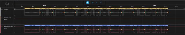
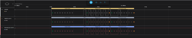
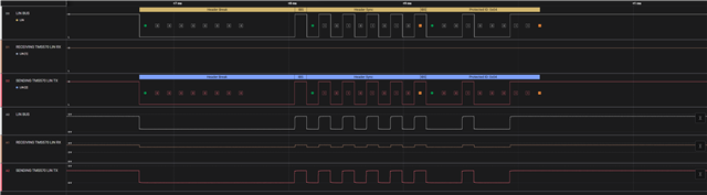
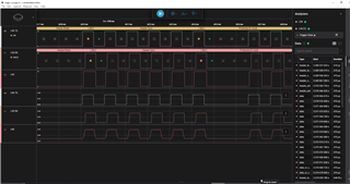
I'm trying to narrow down an issue between either the dev board I am using, or the TJA1028 LIN transceiver I am using. I am using a LAUNCHXL2-570LC43 dev board to try and send a LIN message through two of these transceivers to another LAUNCHXL2-570LC43 board to receive it. However, I am unable to transmit a whole message through the transceiver. For some reason, only the header can make it through the TX line to the LIN line. I measured at the TX line on the board and saw that for some reason it is only sending the header to the transceiver. It's not that the messages are not making it through the transceiver, it's that only the headers are being sent at all. As if the code that deals with sending LIN messages after the header was just erased.
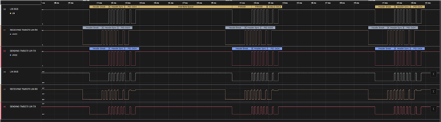
However, whenever I have the exact same code running on the board, but connect the TX and RX lines together, I can clearly see the whole message. In addition, whenever I am communicating with two NUCLEO-H753ZI boards, the entire message is transferred, not just the header. So the transceiver itself is definitely working, and the dev board is working on its own, but the combination of the transceiver with the dev board is causing some issue.
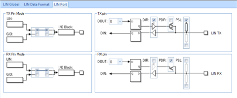
Is there some set up that could potentially prevent the LIN bus on the TMS570LC4357 from sending its message based on the hardware of its setup?
Thanks & Regards,
Ian
Hi Ian,
I hope you removed the "linEnableLoopback" function as shown above and following all other steps properly.
I mean
1. Calling Initialization function
Hi Jagadish,
Yes, I made sure to remove the linEnableLoopback function, and I did follow those necessary steps. I even measured the signal with a logic analyzer while having the LIN RX and TX lines of the board directly connected to one another to make sure I could see the signal, and I did. However, this behavior does not happen when connected to the transceiver instead of itself. In addition to this, the LAUNCHXL2 board is also stopping other devices from communicating with it. Two NUCLEO boards may communicate via a LIN bus made of two transceivers, but when one of those NUCLEO boards is replaced with a LAUNCHXL2 board then the signals from the NUCLEO board may still be seen on the bus, they cannot be seen on the LAUNCHXL2 RX line.
I also made sure to follow all of the steps in the example except for adding in the
Hi Ian,
I am about to debug the project but before that i found the below thread:
It looks similar to our issue, here customer solved the problem by adding parity bits. Could you please try the same on your end?
--
Thanks & regards,
Jagadish.
Hi Jagadish,
I made sure that the ID was calculated to have parity bits in it and I made sure to change the setting in Halcogen to enable ID parity checking. Unfortunately, the issue persists. I decided to try and see if I could communicate between two LAUNCHXL2-570LC43 boards and I set one of them to slave mode. This way, the board in master mode would send messages while the board in slave mode would simply receive messages. Again, the issue persisted.
Thanks & Regards,
Ian
P.S. I did a little more digging around and am absolutely sure that the issue is with the code rather than with the hardware. I say this because I set up two LAUNCHXL2 boards to communicate with one another and found that when the sending board is spamming the LIN bus with messages, but the receiving board is not yet programmed with code, I can see the header on the receiving board's RX line just fine. However, when I program the receiving board, suddenly the RX line of that board can never drop low enough to register any messages.
P.P.S. I have looked into the setup for the code generator, and I made sure to leave RX and TX for LIN floating. I did not enable pull-up or pull-down resistors for either one. Even still, I have not been able to intentionally bring down the voltage of the RX line. However, I did manage to do this by accident. I am working on a setup where I change the target configuration of the project and program the appropriate code onto the appropriate board. However, I accidentally put the code for sending the LIN message onto both of the boards so they both end up sending headers. When the headers collide with each other, then the RX line is able to drop to a low enough voltage to have activity recognized. I don't know why this is the case, but maybe this could be a clue to the issue with the setup?
Hi Ian,
Apologies for the delay in my response, i was stuck with other issues from last few days.
The problem with your issue is that i don't have the TJA1028 LIN transceivers to test this issue on my end.
Can we plan one live debugging session, in this session you can show me the waveforms you are getting, and we can discuss our thoughts.
If you okay with this then I will be available from 10AM to 8PM IST (Indian Standard Time). So based on your convenient we can plan a session.
In mean time, if possible, please send your complete project so that i can do code verification once.
--
Thanks & regards,
Jagadish.
Hi Jagadish,
No worries. I imagine that this must be a rather hectic position. Thank you for returning to my question. Unfortunately, I cannot share with you my entire project as most of it is filled with proprietary secrets. However, I have created a new example project with the same LIN configurations that I have been using for my project. Please find the project below:
I would be available for a live debugging session. However, due to time differences I would really only be available from 10:00 am (Indian Standard Time) to 11:30 am (Indian Standard Time) or from 5:30 pm (Indian Standard Time) to 8:00 pm (Indian Standard Time). How would we communicate with one another in real time? Would either of those times on Monday, January 29 work for you?
I also want to mention that I have learned the cause of one of my issues in the meantime. I was scouring the technical reference manual when I saw on page 1654 that a bit error will cause the microcontroller to abort sending any data almost immediately. I looked through the code and I saw that I was encountering a bit error whenever I did not have the board RX and TX lines directly connected to one another. However, I did not encounter this error when I did have them connected. I researched further and learned that the microcontroller must measure its own message that it sends on the TX line on its RX line and ensure that the data matches. If it does not match, a bit error flag is set. This would explain why I could measure the full message when the MCU was connected to itself, but not in any other circumstance. Because the RX line of the MCU is not dropping low enough in voltage to register as a message (even though some voltage drop is measured which indicates some amount of activity), a bit error must happen which means that the response is never sent.I have been able to pull the RX line low enough when using another dev board so I believe this issue to be related to software rather than hardware. However, I believe if the issue of the RX line voltage never dropping low enough to trigger any measurements, the issue of the LIN never sending a response will also be solved.
Thanks & Regards,
Ian
P.S.
I was able to verify that this was indeed the issue by shorting the RX and TX lines together and then measuring the LIN bus. Sure enough, ensuring that the RX line would measure the sent header and then I could see both the header and the response on the LIN bus. Taking away the shorting connection would result in only the header being visible on the LIN bus again. If the issue of the incorrect voltage level can be solved, everything should be fine.
Hi Ian,
I scheduled a meeting with you on today 6PM.
Here is the meeting link. Let me know if it is not convenient for you.
https://ti.webex.com/ti/j.php?MTID=m789694871338da2bfc7a7e47305ed437
--
Thanks & regards,
Jagadish.
Hi Jagadish,
I apologize for not meeting with you at that time, but I do not see your messages until many hours after you have logged off due to time differences. I would be available to meet with you (preferably at 6PM IST like you suggested) tomorrow, February 1st. I am more readily available for meetings if they are scheduled a day in advance and given with some notice.
Thanks & Regards,
Ian
Hi Ian,
I apologize for not meeting with you at that time, but I do not see your messages until many hours after you have logged off due to time differences.
Totally understood, no issues.
I am creating new link, please join at 6PM today:
https://ti.webex.com/ti/j.php?MTID=md8d5e0a2610522a938995739c7d0166b
--
Thanks & regards,
Jagadish.
Hi Ian,
I just worked on the issue today morning but i couldn't find root cause yet. I am just suspecting may be a voltage levels issue. And i never tested our LIN board with Transceiver yet, so i just ordered one external LIN transceiver board and will be delivered in 3 to 5 days.
I want to test with this board and want to observe the behavior.
I hope this might not be a problem at your end.
--
Thanks & regards,
Jagadish.
Hi Jagadish,
No, that will not be a problem for me. Thank you for letting me know. Just let me know if you can discover anything that I missed before I do. I appreciate all of your help. Do not hesitate to reach out if you need to meet or need more information.
Thanks & Regards,
Ian
Hi Ian,
I understood the root cause for the issue.
The issue is causing by the "TM4C129ENCPDT" IC which is using for XDS110 debug probe.
As you can see the LIN1RX line of the TMS570LC4357 controller is parallelly connected with the U0TX pin of the TM4C129ENCPDT IC.
If we verify the datasheet of the TM4C129ENCPDT controller the default state of this pin is logic High with TTL buffer.
So, due to this event though LIN transceiver trying to transmit the logic low to the TMS570 controller due to TTL Logic High from TM4C129ENCPDT the resultant value is becoming logic high only.
I found this root cause after i tested without connecting the RX line of the launchpad to the LIN.
In this case i observed LIN transceiver was transmitting signal perfectly but once it was connected with Launchpad LIN RX line then it is becoming corrupted.
So, now i changed my application to the LIN2 and tested again because LIN2 RX and TX lines are not connected to any other IC's, so now i got the proper waveform.
Here is my LIN2 application for your reference:
--
Thanks & regards,
Jagadish.
Hi Jagadish,
Is there any way to disable the pull-up resistor on that U0TX pin? To change it to that it's default state is not high? Our company cannot switch over to LIN2 at this stage and I would like to know if there is a workaround for it.
Is this situation also remedied in part by the settings you set for the LIN port in Halcogen? Our project does not use the XDS110 debug probe. We are simply using a dev board that uses the XDS110 to practice setting up LIN communication. Our project uses J-Link. So, we should not be seeing that issue because that IC is not present in our setup. However, we do still see the issue and would it be remedied by having the LIN1 port set up like how you show in your files?
Thanks & Regards,
Ian
Is this situation also remedied in part by the settings you set for the LIN port in Halcogen? Our project does not use the XDS110 debug probe. We are simply using a dev board that uses the XDS110 to practice setting up LIN communication. Our project uses J-Link. So, we should not be seeing that issue because that IC is not present in our setup. However, we do still see the issue and would it be remedied by having the LIN1 port set up like how you show in your files?
Sorry I am not getting this.
Is your hardware have XDS110 (TM4C129ENCPDT) IC or not?
If your project doesn't have TM4C129ENCPDT this IC and doesn't connect this IC UART lines with the controller, then there should not be any issues. LIN should work properly in this case.
If your project has this IC and controller LIN lines connected with this IC like as shown above then one workaround i am thinking is to change the firmware of the XDS110 (TM4C129ENCPDT) debug IC, In its firmware if we change the corresponding UARTTX Line into the some GIO input functionality then issue should be resolve. But i don't know whether we could change that firmware and i don't know how to get its source code.
First i would like to know your hardware connectivity for these LIN1 pins. If possible, draw the hardware connectivity for these lines in some picture and share it to me.
--
Thanks & regards,
Jagadish.
Hi Jagadish,
I mean to say that in our project we do not use the LAUNCHXL2 dev board, so we do not connect to our project using the XDS110 debug probe. We use the Segger J-Link to connect to our project so that cannot be the cause of our issue for the actual project. The reason why I was testing with the LAUNCHXL2 board was so that I could practice LIN communication in order to implement it in our project. However, we do still see the same issue with our board even though we do not use the XDS110 debug probe for it. I tried setting up the LIN1 pins like you had in your example project (like in the picture from my last post), but the issue still persists. Our hardware setup is with a different, but similar LIN transceiver. It is almost the exact same as the setup I showed you before.
Thanks & Regards,
Ian
Hi Ian,
So the LIN lines in your custom hardware were only between controller and transceiver right?
They were not routed to any other parts on the board right?
Can you please make sure that?
—
Thanks & regards,
Jagadish.
Hi Jagadish,
Your example project provided us with the knowledge we needed to get everything working in our project. We just needed to play around with the pull-up/pull-down resistors for the LIN peripheral. I would recommend anyone else having similar trouble with the LIN peripheral do the same.
Thanks & Regards,
Ian
Hi Ian,
So, you are saying that it is working after changing the pull-up/pull-down values?
Can you please tell me what are the exact values you are using and what are your final connections?
--
Thanks & regards,
Jagadish.