This thread has been locked.
If you have a related question, please click the "Ask a related question" button in the top right corner. The newly created question will be automatically linked to this question.
Hello everyone,
I'm trying to use a timer to trigger ADC sampling on LP-MSPM0G3507 (Rev. A) using a zero event.
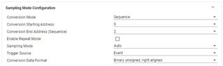
I'm using sysconfig of CCS Theia 1.2.0 to configure module TIMA0: specifically I'm making it to work in periodic down-counting mode, with a period of 50us, and zero events as trigger for ADC, as you can see in the following image:
Running my code I found out that the sampling was happening much faster that expected (TIMA0_CTR changing values too fast considering code), causing some erratic behaviour.
I tried to look for a way to easily measure my code timing, but considering that MSPM0G3507 doesn't seem to have available the possibility to use Clock Counts breakpoints or Profile Clock, i tried using SysTick to have a mean to compare its downcounting to the one of TIMA0: to my surprise SysTick is behaving exactly as expected, having a downcount consistent with my code.
I'm really baffled about this problem, so I'm wondering if it could involve some clocking setting I'm not aware of or something else I'm missing about this system.
The following image is how I configured SYSCTL and SYSTICK and you can find my code.
#include "ti/devices/msp/peripherals/hw_flashctl.h" #include "ti/driverlib/dl_dma.h" #include "ti/driverlib/dl_adc12.h" #include "ti/driverlib/dl_timera.h" #include "ti_msp_dl_config.h" #include <sys/_stdint.h> uint16_t Sample_Buffer[12] = { 0x0000, 0x0000, 0x0000, 0x0000, 0x0000, 0x0000, 0x0000, 0x0000, 0x0000, 0x0000, 0x0000, 0x0000 }; uint16_t test = 0x0000; uint16_t DMA_transfer_control = 0x0000; int main(void) { SYSCFG_DL_init(); DL_DMA_setSrcAddr (DMA, DMA_CH0_CHAN_ID, DL_ADC12_getMemResultAddress(ADC12_0_INST, DL_ADC12_MEM_IDX_0 )); DL_DMA_setDestAddr (DMA, DMA_CH0_CHAN_ID, (uint32_t) &Sample_Buffer[0]); DL_DMA_enableChannel(DMA, DMA_CH0_CHAN_ID); NVIC_EnableIRQ(ADC12_0_INST_INT_IRQN); DL_SYSTICK_enable(); DL_Timer_startCounter(TIMER_0_INST); while (DMA_transfer_control < 0x0003) { __WFI(); } test = 0x1111; while (1) { } } void ADC12_0_INST_IRQHandler(void) { switch (DL_ADC12_getPendingInterrupt(ADC12_0_INST)) { case DL_ADC12_IIDX_DMA_DONE: DMA_transfer_control++; DL_DMA_setSrcAddr (DMA, DMA_CH0_CHAN_ID, DL_ADC12_getMemResultAddress(ADC12_0_INST, DL_ADC12_MEM_IDX_0 )); DL_DMA_setTransferSize(DMA, DMA_CH0_CHAN_ID, 3); DL_DMA_enableChannel(DMA, DMA_CH0_CHAN_ID); DL_ADC12_enableConversions(ADC12_0_INST); break; default: break; } }
Thanks in advance for your help.
Best Regards,
Stefano
Hi Stefano,
How are you determining that the timer is counting too quickly? With a 64MHz TIMCLK period you would have difficulty observing this in the debug window based on the counter value.
If you have access to an Oscope or logic analyzer you could set the TIMA0 load event to trigger a GPIO to toggle and just probe that GPIO.
You can do that entirely in SysConfig by creating an GPIO output, and setting it as an event subscriber. Then enable the zero event of the TIMA0 instance as an event publisher on the same channel.
If everything is being set up correctly you should see that GPIO toggle every 50us when you probe it.
Best Regards,
Brandon Fisher
Going instruction by instruction in the disassembler and comparing it to SYSTICK, that it’s set for the same period of TIMA0, I observe very a different behaviour: in the same period that systick expires TIMA0 trigger 3-4 ADC sample. I’ll try with a scope as soon as possibile, but I don’t have one available at the moment.
Thanks for your answer.
Hi Stefano,
So you are seeing this based on the number of ADC samples that occur in that systick period?
Can you share an image of your ADC settings? Or if you're comfortable sharing your whole .syscfg file I don't mind looking over it. I want to see what the settings are for the Sampling Mode Configuration and the ADC Conversion Memory Configurations.
Best Regards,
Brandon Fisher
Hi Brandon,
sure this are the images you requested regarding my ADC config:
I'm trying to get 3 sample in a period of 50us, period provided by the timer zero event trigger.
What I see right now, given that I'm understanding correctly the feedback from SysTick, is that in the span of 50us I get more then 1 ADC trigger.
Best Regards,
Stefano
Regarding the .sysconfig file I guess it's to big to upload, you can find the generated code here:
ti_msp_dl_config.h
#ifndef ti_msp_dl_config_h #define ti_msp_dl_config_h #define CONFIG_MSPM0G350X #if defined(__ti_version__) || defined(__TI_COMPILER_VERSION__) #define SYSCONFIG_WEAK __attribute__((weak)) #elif defined(__IAR_SYSTEMS_ICC__) #define SYSCONFIG_WEAK __weak #elif defined(__GNUC__) #define SYSCONFIG_WEAK __attribute__((weak)) #endif #include <ti/devices/msp/msp.h> #include <ti/driverlib/driverlib.h> #include <ti/driverlib/m0p/dl_core.h> #ifdef __cplusplus extern "C" { #endif /* * ======== SYSCFG_DL_init ======== * Perform all required MSP DL initialization * * This function should be called once at a point before any use of * MSP DL. */ /* clang-format off */ #define POWER_STARTUP_DELAY (16) #define CPUCLK_FREQ 64000000 /* Defines for TIMER_0 */ #define TIMER_0_INST (TIMA0) #define TIMER_0_INST_IRQHandler TIMA0_IRQHandler #define TIMER_0_INST_INT_IRQN (TIMA0_INT_IRQn) #define TIMER_0_INST_LOAD_VALUE (3199U) #define TIMER_0_INST_PUB_0_CH (1) /* Defines for ADC12_0 */ #define ADC12_0_INST ADC1 #define ADC12_0_INST_IRQHandler ADC1_IRQHandler #define ADC12_0_INST_INT_IRQN (ADC1_INT_IRQn) #define ADC12_0_ADCMEM_0 DL_ADC12_MEM_IDX_0 #define ADC12_0_ADCMEM_0_REF DL_ADC12_REFERENCE_VOLTAGE_INTREF #define ADC12_0_ADCMEM_0_REF_VOLTAGE 2.50 #define ADC12_0_ADCMEM_1 DL_ADC12_MEM_IDX_1 #define ADC12_0_ADCMEM_1_REF DL_ADC12_REFERENCE_VOLTAGE_INTREF #define ADC12_0_ADCMEM_1_REF_VOLTAGE 2.50 #define ADC12_0_ADCMEM_2 DL_ADC12_MEM_IDX_2 #define ADC12_0_ADCMEM_2_REF DL_ADC12_REFERENCE_VOLTAGE_INTREF #define ADC12_0_ADCMEM_2_REF_VOLTAGE 2.50 #define ADC12_0_INST_SUB_CH (1) #define GPIO_ADC12_0_C0_PORT GPIOA #define GPIO_ADC12_0_C0_PIN DL_GPIO_PIN_15 #define GPIO_ADC12_0_C1_PORT GPIOA #define GPIO_ADC12_0_C1_PIN DL_GPIO_PIN_16 #define GPIO_ADC12_0_C2_PORT GPIOA #define GPIO_ADC12_0_C2_PIN DL_GPIO_PIN_17 /* Defines for VREF */ #define VREF_VOLTAGE_MV 2500 #define GPIO_VREF_VREFPOS_PORT GPIOA #define GPIO_VREF_VREFPOS_PIN DL_GPIO_PIN_23 #define GPIO_VREF_IOMUX_VREFPOS (IOMUX_PINCM53) #define GPIO_VREF_IOMUX_VREFPOS_FUNC IOMUX_PINCM53_PF_UNCONNECTED /* Defines for DMA_CH0 */ #define DMA_CH0_CHAN_ID (0) #define ADC12_0_INST_DMA_TRIGGER (DMA_ADC1_EVT_GEN_BD_TRIG) /* clang-format on */ void SYSCFG_DL_init(void); void SYSCFG_DL_initPower(void); void SYSCFG_DL_GPIO_init(void); void SYSCFG_DL_SYSCTL_init(void); void SYSCFG_DL_TIMER_0_init(void); void SYSCFG_DL_ADC12_0_init(void); void SYSCFG_DL_VREF_init(void); void SYSCFG_DL_DMA_init(void); void SYSCFG_DL_SYSTICK_init(void); bool SYSCFG_DL_saveConfiguration(void); bool SYSCFG_DL_restoreConfiguration(void); #ifdef __cplusplus } #endif #endif /* ti_msp_dl_config_h */
ti_msp_dl_config.c
#include "ti_msp_dl_config.h" DL_TimerA_backupConfig gTIMER_0Backup; /* * ======== SYSCFG_DL_init ======== * Perform any initialization needed before using any board APIs */ SYSCONFIG_WEAK void SYSCFG_DL_init(void) { SYSCFG_DL_initPower(); SYSCFG_DL_GPIO_init(); /* Module-Specific Initializations*/ SYSCFG_DL_SYSCTL_init(); SYSCFG_DL_TIMER_0_init(); SYSCFG_DL_ADC12_0_init(); SYSCFG_DL_VREF_init(); SYSCFG_DL_DMA_init(); SYSCFG_DL_SYSTICK_init(); /* Ensure backup structures have no valid state */ gTIMER_0Backup.backupRdy = false; } /* * User should take care to save and restore register configuration in application. * See Retention Configuration section for more details. */ SYSCONFIG_WEAK bool SYSCFG_DL_saveConfiguration(void) { bool retStatus = true; retStatus &= DL_TimerA_saveConfiguration(TIMER_0_INST, &gTIMER_0Backup); return retStatus; } SYSCONFIG_WEAK bool SYSCFG_DL_restoreConfiguration(void) { bool retStatus = true; retStatus &= DL_TimerA_restoreConfiguration(TIMER_0_INST, &gTIMER_0Backup, false); return retStatus; } SYSCONFIG_WEAK void SYSCFG_DL_initPower(void) { DL_GPIO_reset(GPIOA); DL_GPIO_reset(GPIOB); DL_TimerA_reset(TIMER_0_INST); DL_ADC12_reset(ADC12_0_INST); DL_VREF_reset(VREF); DL_GPIO_enablePower(GPIOA); DL_GPIO_enablePower(GPIOB); DL_TimerA_enablePower(TIMER_0_INST); DL_ADC12_enablePower(ADC12_0_INST); DL_VREF_enablePower(VREF); delay_cycles(POWER_STARTUP_DELAY); } SYSCONFIG_WEAK void SYSCFG_DL_GPIO_init(void) { } static const DL_SYSCTL_SYSPLLConfig gSYSPLLConfig = { .inputFreq = DL_SYSCTL_SYSPLL_INPUT_FREQ_16_32_MHZ, .rDivClk2x = 4, .rDivClk1 = 0, .rDivClk0 = 0, .enableCLK2x = DL_SYSCTL_SYSPLL_CLK2X_ENABLE, .enableCLK1 = DL_SYSCTL_SYSPLL_CLK1_DISABLE, .enableCLK0 = DL_SYSCTL_SYSPLL_CLK0_DISABLE, .sysPLLMCLK = DL_SYSCTL_SYSPLL_MCLK_CLK2X, .sysPLLRef = DL_SYSCTL_SYSPLL_REF_SYSOSC, .qDiv = 9, .pDiv = DL_SYSCTL_SYSPLL_PDIV_2, }; SYSCONFIG_WEAK void SYSCFG_DL_SYSCTL_init(void) { //Low Power Mode is configured to be SLEEP0 DL_SYSCTL_setBORThreshold(DL_SYSCTL_BOR_THRESHOLD_LEVEL_0); DL_SYSCTL_setFlashWaitState(DL_SYSCTL_FLASH_WAIT_STATE_2); DL_SYSCTL_setSYSOSCFreq(DL_SYSCTL_SYSOSC_FREQ_BASE); DL_SYSCTL_configSYSPLL((DL_SYSCTL_SYSPLLConfig *) &gSYSPLLConfig); DL_SYSCTL_enableMFCLK(); DL_SYSCTL_setULPCLKDivider(DL_SYSCTL_ULPCLK_DIV_2); DL_SYSCTL_setMCLKSource(SYSOSC, HSCLK, DL_SYSCTL_HSCLK_SOURCE_SYSPLL); DL_SYSCTL_setMCLKDivider(DL_SYSCTL_MCLK_DIVIDER_DISABLE); } /* * Timer clock configuration to be sourced by BUSCLK / (64000000 Hz) * timerClkFreq = (timerClkSrc / (timerClkDivRatio * (timerClkPrescale + 1))) * 64000000 Hz = 64000000 Hz / (1 * (0 + 1)) */ static const DL_TimerA_ClockConfig gTIMER_0ClockConfig = { .clockSel = DL_TIMER_CLOCK_BUSCLK, .divideRatio = DL_TIMER_CLOCK_DIVIDE_1, .prescale = 0U, }; /* * Timer load value (where the counter starts from) is calculated as (timerPeriod * timerClockFreq) - 1 * TIMER_0_INST_LOAD_VALUE = (50 us * 64000000 Hz) - 1 */ static const DL_TimerA_TimerConfig gTIMER_0TimerConfig = { .period = TIMER_0_INST_LOAD_VALUE, .timerMode = DL_TIMER_TIMER_MODE_PERIODIC, .startTimer = DL_TIMER_STOP, }; SYSCONFIG_WEAK void SYSCFG_DL_TIMER_0_init(void) { DL_TimerA_setClockConfig(TIMER_0_INST, (DL_TimerA_ClockConfig *) &gTIMER_0ClockConfig); DL_TimerA_initTimerMode(TIMER_0_INST, (DL_TimerA_TimerConfig *) &gTIMER_0TimerConfig); DL_TimerA_enableClock(TIMER_0_INST); DL_TimerA_enableEvent(TIMER_0_INST, DL_TIMERA_EVENT_ROUTE_1, (DL_TIMERA_EVENT_ZERO_EVENT)); DL_TimerA_setPublisherChanID(TIMER_0_INST, DL_TIMERA_PUBLISHER_INDEX_0, TIMER_0_INST_PUB_0_CH); } /* ADC12_0 Initialization */ static const DL_ADC12_ClockConfig gADC12_0ClockConfig = { .clockSel = DL_ADC12_CLOCK_ULPCLK, .divideRatio = DL_ADC12_CLOCK_DIVIDE_1, .freqRange = DL_ADC12_CLOCK_FREQ_RANGE_24_TO_32, }; SYSCONFIG_WEAK void SYSCFG_DL_ADC12_0_init(void) { DL_ADC12_setClockConfig(ADC12_0_INST, (DL_ADC12_ClockConfig *) &gADC12_0ClockConfig); DL_ADC12_initSeqSample(ADC12_0_INST, DL_ADC12_REPEAT_MODE_DISABLED, DL_ADC12_SAMPLING_SOURCE_AUTO, DL_ADC12_TRIG_SRC_EVENT, DL_ADC12_SEQ_START_ADDR_00, DL_ADC12_SEQ_END_ADDR_02, DL_ADC12_SAMP_CONV_RES_12_BIT, DL_ADC12_SAMP_CONV_DATA_FORMAT_UNSIGNED); DL_ADC12_configConversionMem(ADC12_0_INST, ADC12_0_ADCMEM_0, DL_ADC12_INPUT_CHAN_0, DL_ADC12_REFERENCE_VOLTAGE_INTREF, DL_ADC12_SAMPLE_TIMER_SOURCE_SCOMP0, DL_ADC12_AVERAGING_MODE_DISABLED, DL_ADC12_BURN_OUT_SOURCE_DISABLED, DL_ADC12_TRIGGER_MODE_AUTO_NEXT, DL_ADC12_WINDOWS_COMP_MODE_DISABLED); DL_ADC12_configConversionMem(ADC12_0_INST, ADC12_0_ADCMEM_1, DL_ADC12_INPUT_CHAN_1, DL_ADC12_REFERENCE_VOLTAGE_INTREF, DL_ADC12_SAMPLE_TIMER_SOURCE_SCOMP0, DL_ADC12_AVERAGING_MODE_DISABLED, DL_ADC12_BURN_OUT_SOURCE_DISABLED, DL_ADC12_TRIGGER_MODE_AUTO_NEXT, DL_ADC12_WINDOWS_COMP_MODE_DISABLED); DL_ADC12_configConversionMem(ADC12_0_INST, ADC12_0_ADCMEM_2, DL_ADC12_INPUT_CHAN_2, DL_ADC12_REFERENCE_VOLTAGE_INTREF, DL_ADC12_SAMPLE_TIMER_SOURCE_SCOMP0, DL_ADC12_AVERAGING_MODE_DISABLED, DL_ADC12_BURN_OUT_SOURCE_DISABLED, DL_ADC12_TRIGGER_MODE_AUTO_NEXT, DL_ADC12_WINDOWS_COMP_MODE_DISABLED); DL_ADC12_setPowerDownMode(ADC12_0_INST,DL_ADC12_POWER_DOWN_MODE_MANUAL); DL_ADC12_setSampleTime0(ADC12_0_INST,16); DL_ADC12_enableDMA(ADC12_0_INST); DL_ADC12_setDMASamplesCnt(ADC12_0_INST,3); DL_ADC12_enableDMATrigger(ADC12_0_INST,(DL_ADC12_DMA_MEM2_RESULT_LOADED)); DL_ADC12_setSubscriberChanID(ADC12_0_INST,ADC12_0_INST_SUB_CH); /* Enable ADC12 interrupt */ DL_ADC12_clearInterruptStatus(ADC12_0_INST,(DL_ADC12_INTERRUPT_DMA_DONE)); DL_ADC12_enableInterrupt(ADC12_0_INST,(DL_ADC12_INTERRUPT_DMA_DONE)); DL_ADC12_enableConversions(ADC12_0_INST); } static const DL_VREF_Config gVREFConfig = { .vrefEnable = DL_VREF_ENABLE_ENABLE, .bufConfig = DL_VREF_BUFCONFIG_OUTPUT_2_5V, .shModeEnable = DL_VREF_SHMODE_DISABLE, .holdCycleCount = DL_VREF_HOLD_MIN, .shCycleCount = DL_VREF_SH_MIN, }; SYSCONFIG_WEAK void SYSCFG_DL_VREF_init(void) { DL_VREF_configReference(VREF, (DL_VREF_Config *) &gVREFConfig); } static const DL_DMA_Config gDMA_CH0Config = { .transferMode = DL_DMA_SINGLE_BLOCK_TRANSFER_MODE, .extendedMode = DL_DMA_NORMAL_MODE, .destIncrement = DL_DMA_ADDR_INCREMENT, .srcIncrement = DL_DMA_ADDR_INCREMENT, .destWidth = DL_DMA_WIDTH_HALF_WORD, .srcWidth = DL_DMA_WIDTH_WORD, .trigger = ADC12_0_INST_DMA_TRIGGER, .triggerType = DL_DMA_TRIGGER_TYPE_EXTERNAL, }; SYSCONFIG_WEAK void SYSCFG_DL_DMA_CH0_init(void) { DL_DMA_setTransferSize(DMA, DMA_CH0_CHAN_ID, 3); DL_DMA_initChannel(DMA, DMA_CH0_CHAN_ID , (DL_DMA_Config *) &gDMA_CH0Config); } SYSCONFIG_WEAK void SYSCFG_DL_DMA_init(void){ SYSCFG_DL_DMA_CH0_init(); } SYSCONFIG_WEAK void SYSCFG_DL_SYSTICK_init(void) { /* Initialize the period to 50.00 μs */ DL_SYSTICK_init(3200); }
Hi Stefano,
I don't see anything obvious here in configuration that jumps out at me as wrong. When you say you get 3-4 samples, does that mean 3-4 sequences of conversions? Your ADC is setup in sequence mode so I would expect 3 conversions total from a single trigger.
Testing the timer period with the GPIO output would still be good as well.
Best Regards,
Brandon Fisher
Hi Brandon,
yes, when I wrote 3-4 samples I really meant 3-4 sequences: in each sequence I get 3 samples. What I expect to do is to complete the Sample_buffer in 200us (so 4 ADC triggers, 3 sample for each trigger, 12 samples in total, Sample_buffer array is complete). What I'm experiencing is that, before Systick countdown "expires" I already have a complete Sample_buffer (so it means it took less than 50us to perform 4 ADC triggers).
I'll be able to test it with a scope next monday, in the meantime I'll try to install CCS Theia on another PC to see if maybe it could be somewhat related to what I'm seeing.
Just to be sure, considering I set Systick to 50us, is there any possibility that it is counting differently from TIMA0? I really don't know, maybe some CCS config I'm missing/not considering?
What I can tell you for sure, and if you'll run my code I think you'll be able to see it too, is that Systick performs its countdown in a certain way (I see this by going step-by-step in the disassembler): given that TIMA0 is started at almost the same time as SysTick, I was expecting a time delta between the 2, but this delta should be sort of constant, am I right? Instead I see that TIMA0 is counting down much faster than Systick: could this also be some kind of display issue for the counter reg of TIMA0? I'm really just trying to consider everything possible.
Thanks for your answers and your time.
Stefano
EDIT: Just to be as clear as possibile, I'm looking at SYST_CVR reg to see SysTick countdown.
Just to be sure, considering I set Systick to 50us, is there any possibility that it is counting differently from TIMA0? I really don't know, maybe some CCS config I'm missing/not considering?
It should not be, given that they are sourced from the same clock in your configuration.
What I can tell you for sure, and if you'll run my code I think you'll be able to see it too, is that Systick performs its countdown in a certain way (I see this by going step-by-step in the disassembler): given that TIMA0 is started at almost the same time as SysTick, I was expecting a time delta between the 2, but this delta should be sort of constant, am I right? Instead I see that TIMA0 is counting down much faster than Systick: could this also be some kind of display issue for the counter reg of TIMA0? I'm really just trying to consider everything possible.
The delta should remain constant. The inclusion of the debugger in the mix can cause some strange behavior though. TIMA0 defaults to free run mode, meaning that it continues to run while the core is halted by the debugger.
Whereas the SysTick halts when the debugger pauses the CPU:
Using the debugger will pull these two out of sync, as it is periodically going to halt execution to get the debug state.
Best Regards,
Brandon Fisher
Ok great, so this really should be a non-issue.
Just to be sure I'll still check with the scope next monday, but I think this is it, I'll set the topic as solved as soon as I'll do this test,
Thanks for you answers and insights, and sorry if my question was silly, considering this is almost certainly not a problem.
Best Regards,
Stefano
EDIT: Actually I don't need to see it on the scope, using DL_Timer_setCoreHaltBehavior(TIMER_0_INST, DL_TIMER_CORE_HALT_IMMEDIATE) I could see that the counter was working propertly. Thanks again.