Other Parts Discussed in Thread: LP-AM263
Hello Team,
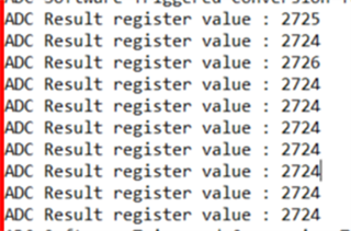
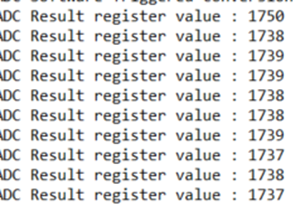
I have tested adc_soc_software project in the MCU PLUS SDK folder. While measuring i can see the difference of more than 0.3v with voltage given and teh vaue printed in the software.
| Voltage Given(in volts) | ADC Result printed in the software | Difference between printed value and given voltage(In volts) |
| 3.073 | 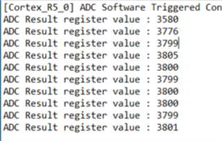 |
0.18 |
| 2.684 |  |
0.3 |
| 2.747 |  |
0.325 |
| 2.264 | 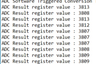 |
0.803 |
Is there any error percentage tolerance? What could be the reason for this much difference?
Thanks
Aswathy Jg