This thread has been locked.

If you have a related question, please click the "Ask a related question" button in the top right corner. The newly created question will be automatically linked to this question.

TM4C1294NCPDT: I2C Lines Held trying to read TMP117

Part Number: TM4C1294NCPDT
Other Parts Discussed in Thread: TMP117, INA233, , TM4C1230H6PM

Hello, 

Reposting on this forum because it didn't seem to get much traction on the sensor forum. 

(Using the TM4C1294NCPDTI3 to talk to TMP117).

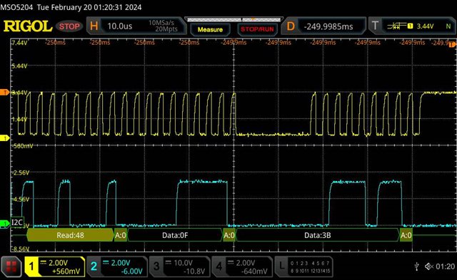
I am having I2C problems in which my i2c line seems to get stuck. The state where it's stuck is CLK held high and DATA held low. 

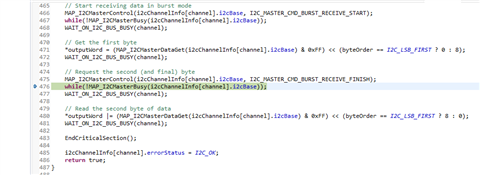
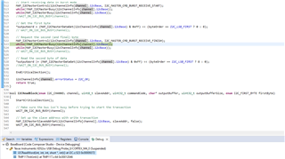
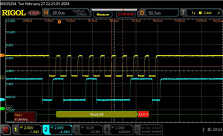
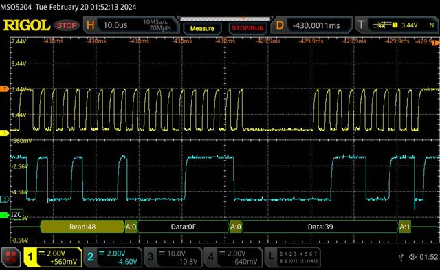
This has consistently happened after writing to the Configuration Register (01h) and reading back the 16-bit response. In the screenshots I took from the oscilloscope it looks like the data values are getting through but seem to have a problem getting the NACK and stop condition from the master. Is there any reason for this failure or how to avoid it? The problem is very inconsistent. 

Other things to note are that are 4 INA233 on the i2c bus, an ADXL355BEZ accelerometer, and this TMP117 temperature sensor. 

In all of the failures, the temperature sensor was always the peripheral that held the line. 
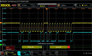
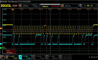
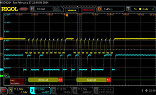
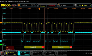
YELLOW IS CLK

BLUE IS DATA

See failure waveform:

This is the successful transaction earlier in the loop: 

Any ideas or advice would be helpful 

  • Hi,

      Not sure if you have the similar problem as in the below post. 

    https://e2e.ti.com/support/power-management-group/power-management/f/power-management-forum/844446/tpsm846c23evm-806-why-ic2-needs-certain-delay-in-tpsm846c23evm-806-for-every-data-byte-transmission

      I don't see your code snippet. But basically, wherever you have a statement like one below in your code, replace with the 

    REPLACE below line everywhere in your code.

    while(I2CMasterBusy(I2C1_BASE));

    WITH below two lines.
    while(!I2CMasterBusy(I2C1_BASE)); // Add this line on top of the original line. 
    while(I2CMasterBusy(I2C1_BASE));


  • Hi Charles, thanks for the reply.  I'm working with Shaun on this issue.  Here's the code we're using to do the read from the TMP117 shown in the above oscilloscope screenshots:

    We make this function call from our TMP117 module:

    Fullscreen
    1
    I2CReadWord(i2cChannel, SLAVE_ADDRESS, TEMP_RESULT_REG, &tempValue, I2C_MSB_FIRST);
    XXXXXXXXXXXXXXXXXXXXXXXXXXXXXXXXXXXXXXXXXXXXXXXXXX

    Which calls into this I2C function (note the start/end critical section functions just disable/enable interrupts so the I2C transaction does not get interrupted):

    Fullscreen
    1
    2
    3
    4
    5
    6
    7
    8
    9
    10
    11
    12
    13
    14
    15
    16
    17
    18
    19
    20
    21
    bool I2CReadWord(enum I2C_CHANNEL channel, uint8_t slaveAddress, uint8_t registerAddress, int16_t* outputWord, enum I2C_BYTE_ORDER byteOrder)
    {
    StartCriticalSection();
    // Make sure the bus isn't busy before trying to start the transaction
    WAIT_ON_I2C_BUS_BUSY(channel);
    // Set up the slave address with write transaction
    MAP_I2CMasterSlaveAddrSet(i2cChannelInfo[channel].i2cBase, slaveAddress, false);
    WAIT_ON_I2C_BUS_BUSY(channel);
    // Store the command data in I2C data register
    MAP_I2CMasterDataPut(i2cChannelInfo[channel].i2cBase, registerAddress);
    WAIT_ON_I2C_BUS_BUSY(channel);
    // Start the I2C transaction
    MAP_I2CMasterControl(i2cChannelInfo[channel].i2cBase, I2C_MASTER_CMD_BURST_SEND_START);
    WAIT_ON_I2C_BUS_BUSY(channel);
    // Set the data direction to true since the I2C Master is initiating a read from the slave
    MAP_I2CMasterSlaveAddrSet(i2cChannelInfo[channel].i2cBase, slaveAddress, true);
    XXXXXXXXXXXXXXXXXXXXXXXXXXXXXXXXXXXXXXXXXXXXXXXXXX

    The WAIT_ON_I2C_BUS_BUSY is a macro:

    Fullscreen
    1
    #define WAIT_ON_I2C_BUS_BUSY(CHANNEL) if(I2CWaitOnMasterBusy(CHANNEL) == false) { EndCriticalSection(); return false; }
    XXXXXXXXXXXXXXXXXXXXXXXXXXXXXXXXXXXXXXXXXXXXXXXXXX

    And the I2CWaitOnMasterBusy function is this:

    Fullscreen
    1
    2
    3
    4
    5
    6
    7
    8
    9
    10
    11
    12
    13
    14
    15
    16
    17
    18
    19
    20
    21
    bool I2CWaitOnMasterBusy(enum I2C_CHANNEL channel)
    {
    uint32_t tries = 0;
    while(MAP_I2CMasterBusy(i2cChannelInfo[channel].i2cBase) && tries < timeoutTries)
    {
    TimeDelayMicroseconds(timeoutWaitUs);
    ++tries;
    }
    // Check one last time if the I2C bus is busy
    if(MAP_I2CMasterBusy(i2cChannelInfo[channel].i2cBase))
    {
    // Get any error status that might exist
    i2cChannelInfo[channel].tivaErrorStatus = MAP_I2CMasterErr(i2cChannelInfo[channel].portBase);
    i2cChannelInfo[channel].errorStatus = I2C_BUS_BUSY_TIMEOUT;
    return false;
    }
    i2cChannelInfo[channel].errorStatus = I2C_OK;
    return true;
    XXXXXXXXXXXXXXXXXXXXXXXXXXXXXXXXXXXXXXXXXXXXXXXXXX

    I'm concerned about adding the while(!I2CMasterBusy()); call to I2CWaitOnMasterBusy since in cases where the bus never goes busy we'll wait indefinitely.

  • Hi Terence,

      There is a known race condition in the hardware where the BUSY bit is not set early enough when the processor tries to poll for its status. This is the reason to insert  while(!I2CMasterBusy()) before  while(I2CMasterBusy()). Please refer to an example in C:\ti\TivaWare_C_Series-2.2.0.295\examples\boards\ek-tm4c1294xl-boostxl-senshub\humidity_sht21_simple on how they are used. Below is a snippet. Although I don't know for sure your specific issue is related to this known issue, but I want to first rule it out. 

    Fullscreen
    1
    2
    3
    4
    5
    6
    7
    8
    9
    10
    11
    12
    13
    14
    15
    16
    17
    18
    19
    20
    21
    void
    I2CReadCommand(uint32_t * pui32DataRx)
    {
    //
    // Modify the data direction to true, so that seeing the address will
    // indicate that the I2C Master is initiating a read from the slave.
    //
    MAP_I2CMasterSlaveAddrSet(I2C7_BASE, SHT21_I2C_ADDRESS, true);
    //
    // Setup for first read. Use I2C_MASTER_CMD_BURST_RECEIVE_START
    // to start a burst mode read. The I2C master continues to own
    // the bus at the end of this transaction.
    //
    MAP_I2CMasterControl(I2C7_BASE, I2C_MASTER_CMD_BURST_RECEIVE_START);
    //
    // Wait until master module is done transferring.
    // The I2C module has a delay in setting the Busy flag in the register so
    // there needs to be a delay before checking the Busy bit. The below loops
    // wait until the Busy flag is set, and then wait until it is cleared to
    XXXXXXXXXXXXXXXXXXXXXXXXXXXXXXXXXXXXXXXXXXXXXXXXXX

  • There is a known race condition in the hardware where the BUSY bit is not set early enough when the processor tries to poll for its status. This is the reason to insert  while(!I2CMasterBusy()) before  while(I2CMasterBusy()). Please refer to an example in C:\ti\TivaWare_C_Series-2.2.0.295\examples\boards\ek-tm4c1294xl-boostxl-senshub\humidity_sht21_simple on how they are used. Below is a snippet. Although I don't know for sure your specific issue is related to this known issue, but I want to first rule it out. 

    Thanks, Charles.  I understand what you're saying, but you agree with inserting the while(!I2CMasterBusy()) we run the risk of blocking indefinitely if we encounter a situation where the BUSY bit is set early enough, right?

    Also, the code I pasted above is being used on multiple boards with various I2C devices (dozens) and works fine 99.9999% of the time.  If I2CMasterBusy() was returning false in my I2CWaitOnMasterBusy() function above, before turning true for the I2C transaction, I believe we would much more frequently see bad transactions due to I2CWaitOnMasterBusy() completing too soon.  No?

  • I understand what you're saying, but you agree with inserting the while(!I2CMasterBusy()) we run the risk of blocking indefinitely if we encounter a situation where the BUSY bit is set early enough, right?

    Hi Terence,

      Sorry, I don't agree until you have tried it and confirm it does not work. 

    Also, the code I pasted above is being used on multiple boards with various I2C devices (dozens) and works fine 99.9999% of the time.  If I2CMasterBusy() was returning false in my I2CWaitOnMasterBusy() function above, before turning true for the I2C transaction, I believe we would much more frequently see bad transactions due to I2CWaitOnMasterBusy() completing too soon.  No?

    Per my understanding of your application, after reading two bytes, the I2Cis supposed to assert NACK to stop further reading. I have yet to fully know if the missing NACK is related to the known issue. Please see another post for which adding the while(!I2CMasterBusy()) resolves a missing byte issue. This is why I'd like you to try to rule out your issue has nothing to do with having while(!I2CMasterBusy()) or not. 

    https://e2e.ti.com/support/microcontrollers/arm-based-microcontrollers-group/arm-based-microcontrollers/f/arm-based-microcontrollers-forum/741685/tm4c1294ncpdt-i2c-multiple-data-byte-transfer-bytes-being-skipped

  • Hi Charles - Yes, no problem, I will try.  One question: In the code example you posted it only shows the while(!I2CMasterBusy()) calls being made after MAP_I2CMasterControl() calls.  Do you agree that is the only time I should do while(!I2CMasterBusy()) calls?

    For example, do you agree I should make my I2CReadWord() function look like this (note the while(!I2CMasterBusy()) calls only after my MAP_I2CMasterControl() calls:

    Fullscreen
    1
    2
    3
    4
    5
    6
    7
    8
    9
    10
    11
    12
    13
    14
    15
    16
    17
    18
    19
    20
    21
    bool I2CReadWord(enum I2C_CHANNEL channel, uint8_t slaveAddress, uint8_t registerAddress, int16_t* outputWord, enum I2C_BYTE_ORDER byteOrder)
    {
    StartCriticalSection();
    // Make sure the bus isn't busy before trying to start the transaction
    WAIT_ON_I2C_BUS_BUSY(channel);
    // Set up the slave address with write transaction
    MAP_I2CMasterSlaveAddrSet(i2cChannelInfo[channel].i2cBase, slaveAddress, false);
    WAIT_ON_I2C_BUS_BUSY(channel);
    // Store the command data in I2C data register
    MAP_I2CMasterDataPut(i2cChannelInfo[channel].i2cBase, registerAddress);
    WAIT_ON_I2C_BUS_BUSY(channel);
    // Start the I2C transaction
    MAP_I2CMasterControl(i2cChannelInfo[channel].i2cBase, I2C_MASTER_CMD_BURST_SEND_START);
    while(!MAP_I2CMasterBusy(i2cChannelInfo[channel].i2cBase));
    WAIT_ON_I2C_BUS_BUSY(channel);
    // Set the data direction to true since the I2C Master is initiating a read from the slave
    XXXXXXXXXXXXXXXXXXXXXXXXXXXXXXXXXXXXXXXXXXXXXXXXXX

  • Hi Terence,  

      The example I have shows the below where while(!MAP_I2CMasterBusy(I2C7_BASE)) precedes while(MAP_I2CMasterBusy(I2C7_BASE)) after every call to MAP_I2CMasterControl(). 

    //
    // Modify the data direction to true, so that seeing the address will
    // indicate that the I2C Master is initiating a read from the slave.
    //
    MAP_I2CMasterSlaveAddrSet(I2C7_BASE, SHT21_I2C_ADDRESS, true);

    //
    // Setup for first read. Use I2C_MASTER_CMD_BURST_RECEIVE_START
    // to start a burst mode read. The I2C master continues to own
    // the bus at the end of this transaction.
    //
    MAP_I2CMasterControl(I2C7_BASE, I2C_MASTER_CMD_BURST_RECEIVE_START);

    //
    // Wait until master module is done transferring.
    // The I2C module has a delay in setting the Busy flag in the register so
    // there needs to be a delay before checking the Busy bit. The below loops
    // wait until the Busy flag is set, and then wait until it is cleared to
    // indicate that the transaction is complete. This can take up to 633 CPU
    // cycles @ 100 kbit I2C Baud Rate and 120 MHz System Clock. Therefore, a
    // while loop is used instead of SysCtlDelay.
    //
    while(!MAP_I2CMasterBusy(I2C7_BASE))
    {
    }
    while(MAP_I2CMasterBusy(I2C7_BASE))
    {
    }

    //
    // Read the first byte data from the slave.
    //
    pui32DataRx[0] = MAP_I2CMasterDataGet(I2C7_BASE);

    //
    // Setup for the second read. Use I2C_MASTER_CMD_BURST_RECEIVE_CONT
    // to continue the burst mode read. The I2C master continues to own
    // the bus at the end of this transaction.
    //
    MAP_I2CMasterControl(I2C7_BASE, I2C_MASTER_CMD_BURST_RECEIVE_CONT);

    //
    // Wait until master module is done transferring.
    //
    while(!MAP_I2CMasterBusy(I2C7_BASE))
    {
    }
    while(MAP_I2CMasterBusy(I2C7_BASE))
    {
    }

    //
    // Read the second byte data from the slave.
    //
    pui32DataRx[1] = MAP_I2CMasterDataGet(I2C7_BASE);

    //
    // Setup for the third read. Use I2C_MASTER_CMD_BURST_RECEIVE_FINISH
    // to terminate the I2C transaction. At the end of this transaction,
    // the STOP bit will be issued and the I2C bus is returned to the
    // Idle state.
    //
    MAP_I2CMasterControl(I2C7_BASE, I2C_MASTER_CMD_BURST_RECEIVE_FINISH);

    //
    // Wait until master module is done transferring.
    //
    while(!MAP_I2CMasterBusy(I2C7_BASE))
    {
    }
    while(MAP_I2CMasterBusy(I2C7_BASE))
    {
    }

    //
    // Note the third 8-bit data is the checksum byte. It will be
    // left to the users as an exercise if they want to verify if the
    // checksum is correct.
    pui32DataRx[2] = MAP_I2CMasterDataGet(I2C7_BASE);

  • Right, I just wanted to confirm that I should not be using while(!I2CMasterBusy()) calls after the other Tivaware calls like MAP_I2CMasterSlaveAddrSet and MAP_I2CMasterDataGet.

  • Hi Charles - I added the while(!I2CMasterBusy()) calls after the MAP_I2CMasterControl() calls as suggested and it appears to be stuck on one of them.

    I'm using an XDS200 to debug.  When I break I see this:


    Note that is near the end of my I2CReadWord() function I previously posted.

    Any other suggestions?

  • Hi Terence,

      I'm curious what I2C speed you are operating. Is it 100k or higher?

      I hate to ask you to try things that don't provide positive result. Can you please just try something simple like below code and determine if it makes a difference. if it is working then you can gradually add back other things that you currently have in your WAIT_ON_I2C_BUS_BUSY which includes error checks. 


    Fullscreen
    1
    2
    3
    4
    5
    6
    7
    8
    9
    10
    11
    12
    13
    14
    15
    16
    17
    18
    19
    20
    21
    bool I2CReadWord(enum I2C_CHANNEL channel, uint8_t slaveAddress, uint8_t registerAddress, int16_t* outputWord, enum I2C_BYTE_ORDER byteOrder)
    {
    StartCriticalSection();
    // Make sure the bus isn't busy before trying to start the transaction
    // WAIT_ON_I2C_BUS_BUSY(channel); // Comment this out for now
    // Set up the slave address with write transaction
    MAP_I2CMasterSlaveAddrSet(i2cChannelInfo[channel].i2cBase, slaveAddress, false);
    //WAIT_ON_I2C_BUS_BUSY(channel); // This is not really needed as the above function does not involve the bus
    // Store the command data in I2C data register
    MAP_I2CMasterDataPut(i2cChannelInfo[channel].i2cBase, registerAddress);
    // WAIT_ON_I2C_BUS_BUSY(channel); // This is not really needed as the above function does not involve the bus
    // Start the I2C transaction
    MAP_I2CMasterControl(i2cChannelInfo[channel].i2cBase, I2C_MASTER_CMD_BURST_SEND_START);
    // while(!MAP_I2CMasterBusy(i2cChannelInfo[channel].i2cBase));
    // WAIT_ON_I2C_BUS_BUSY(channel);
    while(MAP_I2CMasterBusy(i2cChannelInfo[channel].i2cBase)); // For send, just use MAP_I2CMasterBusy, not !MAP_I2CMasterBusy
    XXXXXXXXXXXXXXXXXXXXXXXXXXXXXXXXXXXXXXXXXXXXXXXXXX

  • Hi Charles - Thanks for the reply, I haven't had a chance to run your suggested test, hopefully tomorrow, but just a couple quick data points:

    • Our I2C bus is running at 400 KPBS
    • In the test results shown previously where we were stuck on while(!MAP_I2CMasterBusy()), this was on a custom board, the same board Shaun showed the oscilloscope screenshots at the top of this thread.  However, yesterday, I ran the same code on the Tiva dev board connected to the Adafruit TMP117 breakout board and it did not get stuck on any of the while(!MAP_I2CMasterBusy()) calls.  I let it run for over an hour and it was querying the TMP117 roughly five times per second.  When doing this test on our custom board it got stuck in the while loop immediately at startup where the firmware attempts to configure the TMP117.
  • Hi Terence,

      I suggest you test the modified code I sent earlier and run it on the LaunchPad. If it works, then rerun it on your custom board. If there is a different result, then it may suggest some board level difference that caused your problem on the custom board. 

  • Hi Charles - I did as you suggested.  The code works when running on the Tiva Dev Board with the Adafruit TMP117 breakout board connected.

    For our custom board, we have two different setups: One setup where the board is installed on a full system (with other boards and electronics) and another setup at Shaun's desk which only includes our custom board and a power supply.

    I did one test on the full system late Friday and the code worked.  I was not able to let it run for very long though.

    When testing the same code at Shaun's desk the I2CReadWord function hung indefinitely when doing initialization of the TMP117.  The initialization step just attempts to read the device ID register (0x0F) at startup of the firmware.  Here's a screenshot from CCS showing where the code was hanging indefinitely:

  • Hi Terence,

    another setup at Shaun's desk which only includes our custom board and a power supply.

      If it fails on all three setups (LaunchPad, full custom setup and Shaun's desktop setup) then it would have been a bit easier to diagnose. But now, two out three setups are working then it kind of indicate there is some difference between Shaun's local setup vs. the other two). A couple of questions and suggestions:

      - Did you only connect the custom board on Shaun's desk to the Adafruit TMP117 and nothing else? You said at Shaun's desk is only the custom board and a power supply. If there is no slave (e.g. TMp117) connected to the board then how can the master read the register?

      - Is the custom board similar to the full setup that has other components (e.g. INA233  and others) on the bus?

      - You said running the same code, the LaunchPad connected to the Adafruid TMP117 will work but not Sharun's board. Can you show the waveform for both when reading the ID register?

      - What is the pull up resistor value on SCL and SDA bus on your LaunchPad setup vs Shaun's local setup?

      - Can any I2C slave on your setup have the capability to stretch the SCL clock as a means to wait? Per I2C protocol, if a slave is not ready to respond, it can hold the SCL low as a wait state. Just wanted to know if you run into such a situation. Without the waveform, I can't really tell. 

      - In your very first problem description, you said it works 99.999% of time but now it seems it is dead on initialization. I'm a bit confused on what is the difference. Are we talking about different setups or the same setup?

      - For experiment, what if you lower the I2C speed to 100k vs 400k?

      - While it is stuck at line 523 for Shaun's board, can you check the I2CMCS status register? Do you see any flags?

      - For experiment, on line 523, can you replace with a fixed loop? I want to know if it makes a difference. For example, replace with:

        for (i=0;i<1000;i++); 

  • Hi Charles, thanks for the reply, I've replied inline below to each of your questions:

    two out three setups are working then it kind of indicate there is some difference between Shaun's local setup vs. the other two).

    Yes, but we've seen intermittent success/failures with the custom board in both setups.  We've not seen any issues with the Launchpad setup.  The Launchpad setup will always read the ID correctly and get the correct temperature.  Earlier this morning I let the Launchpad setup run for nearly 45 minutes.  It reads the TMP117 multiple times per second.  There were no issues. 

    Did you only connect the custom board on Shaun's desk to the Adafruit TMP117 and nothing else? You said at Shaun's desk is only the custom board and a power supply. If there is no slave (e.g. TMp117) connected to the board then how can the master read the register?

    The Launchpad setup is the only setup using the Adafruit TMP117 breakout board.  The custom board has a TMP117 installed on the board.

    Is the custom board similar to the full setup that has other components (e.g. INA233  and others) on the bus?

    The hardware is identical on the two custom boards.  However, for these latest tests, the firmware we've been running on the custom board at Shaun's desk I've disabled the I2C communication to all components except for the TMP117 so that it is as identical as possible to the Launchpad setup.

    Can you show the waveform for both when reading the ID register?

    Sure, here is the waveform for the custom board at Shaun's desk when attempting to read the ID:

    And here is the Launchpad successfully reading the ID:

    What is the pull up resistor value on SCL and SDA bus on your LaunchPad setup vs Shaun's local setup?

    I have the LaunchPad connected directly to the Adafruit TMP117 with jumpers.  The schematic of the TMP117 breakout board states it has 10K pull up resistors on it and I confirmed this.  Our custom board has 1.65K pullups.

    Can any I2C slave on your setup have the capability to stretch the SCL clock as a means to wait? Per I2C protocol, if a slave is not ready to respond, it can hold the SCL low as a wait state. Just wanted to know if you run into such a situation. Without the waveform, I can't really tell. 

    No clock stretching that I'm aware of, and I think with these latest tests it's a moot point since the firmware is only attempting to communicate with the TMP117.

    In your very first problem description, you said it works 99.999% of time but now it seems it is dead on initialization. I'm a bit confused on what is the difference. Are we talking about different setups or the same setup?

    Different setups.  Other than this custom board that we're having trouble with, we have four other different custom boards designs (entirely different board designs, and multiple boards for each design).  These other custom boards all have TMP117 sensors on them and are using a Tiva (TM4C1294NCPDT or TM4C1230H6PM) running the same exact firmware and they work fine.  Apologies for saying 99.9999% I should've just said 100% of the time.

    For experiment, what if you lower the I2C speed to 100k vs 400k?

    Same result with the code hanging on the same line, but less I2C traffic on the scope.  Maybe the lower speed allows less data to transfer before the firmware hangs on the while loop?:

    While it is stuck at line 523 for Shaun's board, can you check the I2CMCS status register? Do you see any flags?

    Yes, I2C_MCS_IDLE and I2C_MCS_QCMD are both high.  Here's a screenshot:

    For experiment, on line 523, can you replace with a fixed loop? I want to know if it makes a difference. For example, replace with:

        for (i=0;i<1000;i++); 

    We tried this in both debug and release builds.  It now of course did not get stuck on the while loop (since we removed it) but it still did not read the ID.  We captured waveforms for this as well.  I pasted the debug build waveform first below and the release build waveform next.  It's interesting how the first transaction for the release is showing a read when it shows a write for the debug version.  I wonder if the compiler is optimizing out the for loop in the release build.

  • Sure, here is the waveform for the custom board at Shaun's desk when attempting to read the ID:

    Hi Terence,

      In this scope cap, it seems like you are first writing to slave address 0x48 but you are getting a NACK from the slave, isn't? Do you know why TMP117 is NACKing to the master? I'm not familiar with TMP117 to know the reason. 

    Same result with the code hanging on the same line, but less I2C traffic on the scope.  Maybe the lower speed allows less data to transfer before the firmware hangs on the while loop?:

    Here at 100k, you are reading from slave address 0x48. The slave again replies with NACK. I think you need to investigate why slave is not responding with a ACK? When the transmitter receives a NACK, it will abort the transaction and abort with the STOP.

    We tried this in both debug and release builds.  It now of course did not get stuck on the while loop (since we removed it) but it still did not read the ID.  We captured waveforms for this as well.  I pasted the debug build waveform first below and the release build waveform next.  It's interesting how the first transaction for the release is showing a read when it shows a write for the debug version.  I wonder if the compiler is optimizing out the for loop in the release build.

    In this cap, the slave again replies with NACK. I don't think compiler will  optimize out for (i=0;i<1000;i++). 

    Please compare your custom board as far as all IN and OUT connections to TMP117 to your other working designs and LaunchPad. From what I can tell on your scope caps, the slave is not responding for some reason. When a slave is responding with NACK, it normally means it is not ready yet. 

    Is it possible to connect the TMP117 breakout board to your custom board and somehow disable your current on-board TMP117 chip?

  • Hi Charles - Big apology.  It appears the TMP117 sensor on the custom board at Shaun's desk was damaged and not responding.  Shaun replaced it with a new one and it immediately started responding with the expected reply just like with the Launchpad and Adafruit TMP117 setup.

    We're going to start adding back the other sensors.  I'll make sure those sensors use the while(!MAP_I2CMasterBusy()) calls where appropriate when they do reads and writes.  Fingers crossed that resolves our problems.

    We'll keep you posted.  We very much appreciate all of your assistance with this.

  • Hi Terence,

      Based on your status in this post, https://e2e.ti.com/support/microcontrollers/arm-based-microcontrollers-group/arm-based-microcontrollers/f/arm-based-microcontrollers-forum/1336570/tm4c1294ncpdt-odd-i2c-error-occurring I suppose the I2C issue is resolved. I will close this thread for now. If you have any update, you can write back to the post and the status will change to OPEN. 

  • Charles, these are separate issues. Although, we might have solved this issue. For reference, the issue was that the accelerometer device ADXL355BEZ had issues sharing an SDA bus. According to the datasheet for the ADXL355BEZ:

    "The ADXL355 supports point-to-point I2 C communication. However, when sharing an SDA bus, the ADXL355 may prevent communication with other devices on that bus. If at any point, even when the ADXL355 is not being addressed, the 0x3A and 0x3B bytes (when the ADXL355 device address is set to 0x1D), or the 0xA6 and 0xA7 bytes (when the ADXL355 device address is set to 0x53) are transmitted on the SDA bus, the ADXL355 responds with an acknowledge bit and pulls the SDA line down. For example, this response can occur when reading or writing the data bytes (0x3A/0x3B or 0xA6/0xA7) to another sensor on the bus. When the ADXL355 pulls the SDA line down, communication with other devices on the bus may be interrupted. To resolve this interruption, the ADXL355 must be connected to a separate SDA bus, or the CS/SCL pin must be switched high when communication with the ADXL355 is not desired (it is normally grounded). "

    I am currently testing the ADXL355BEZ on its own SDA line (separate I2C Bus) and it seems to have fixed the issue. Thanks for all your help.