This thread has been locked.

If you have a related question, please click the "Ask a related question" button in the top right corner. The newly created question will be automatically linked to this question.

AM2634: RTI0 Clock Source: Pros and Cons of Different Clock Sources

Part Number: AM2634
Other Parts Discussed in Thread: SYSCONFIG

Hello,

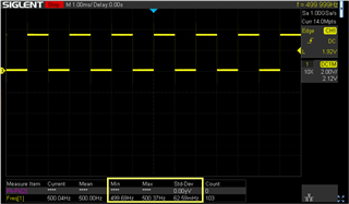
We need a 100us OS tick for our FreeRTOS implementation using the Clock configuration in SYSCONFIG. I see the default WUCPUCLK (25MHz on the EVM) is used for all the examples I've opened so far.

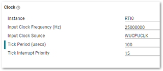
1) My understanding then is that we can generate the 100us tick with a resolution of 40ns (1 / 25MHz). Have I understood that correctly please? If so, this sounds plenty good enough to me.

2) Is there any merit to choosing a different clock source (e.g. DPLL_PER_HSDIV0_CLKOUT1) with a higher frequency to generate our 100us tick apart from the obvious higher resolution?

Thank you.

  • Hello Kier,

    1) Your understanding here is correct.

    2) Routing a higher frequency clock through the SoC will result in a higher power consumption. It is recommended to use the default frequencies whenever possible as this will provide the most accurate HW implementation of the configuration provided in the Power Estimation Tool.

    Best Regards,

    Zackary Fleenor

  • Thank you very much Zackary. That is very topical since we are indeed looking at power consumption.

  • Just for the completeness, I compared some of the clock sources for stability using a toggling GPIO pin from a 1ms FreeRTOS task.

    RTI0 Clock Core0_1ms GPIO Toggle Frequency (Hz)
    Source Source Freq Min. Max. Std Dev
    WUCPUCLK 25MHz 495.87 508.4 1.31
    DPLL_PER_HSDIV0_CLKOUT1 192MHz 499.93 500.07 0.02
    DPLL_CORE_HSDIV0_CLKOUT1 500Mhz 499.95 500.06 0.02
    XTALCLK 25MHz 499.69 500.37 0.06
    SYS_CLK 200MHz 499.93 500.08 0.02

    For reasons unknown, the WUCPUCLK performs much worse than XTALCLK*. Given the power consumption argument above, the best option seems to be XTALCLK rather than WUCPUCLK.

    Here's the scope screenshot for XTALCLK result above

    *Any idea why this might be Zackary?

  • Thanks for sharing this data. What was the methodology and timespan for which this data was taken?

    I am looping in some design experts to help provide a response and will provide feedback once available. 

    Best Regards,

    Zackary Fleenor

  • Thanks for the response.

    What was the methodology and timespan

    I allowed the scope to take approx 100 samples. I think it samples once per second so that is ~1m 40s. I don't have any other info on how the scope makes the statistical calculation.

    Perhaps the next step is that I should make a project that replicates the phenomenon that I can handover to you to. I'll see if I can do that next week.

  • That would be great if you could share your example for us to replicate. We will continue to dig in to the topic in the meantime.

    Thanks and Regards,

    Zackary Fleenor

  • Hello Kier, wanted to check in here and see if you can share your example code to replicate what you are seeing on our side.

    Best,

    Zackary Fleenor

  • Hi Zackary, Sorry, yes, still on my TODO. Will try to do this today.

  • OK, I tried to replicate the problem with a project based on FreeRTOS blinky but could not see the issue. I guess there must be some other factors at play. Let's close this I think. Thanks for following up anyway.

  • Sounds good! Thanks Kier. My initial thoughts go to the test setup, if different probes or cables were used, any difference in the active load experienced by the pin during measurement would create a low-pass filter and impact the rise/fall rates of the signal and lead to the delta found previously. Please feel free to reach back out if any further questions arise.

    Best Regards,

    Zackary Fleenor