Part Number: TMS570LC4357
Other Parts Discussed in Thread: HALCOGEN
Hello Team,
We are using TMS570LC4357 evaluation board in which we are testing internal ADC.
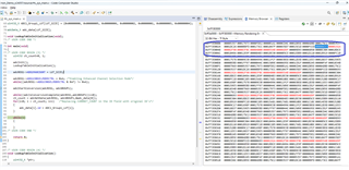
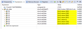
So far we have tried to get data in single/continuous conversion mode and got the results as intended.
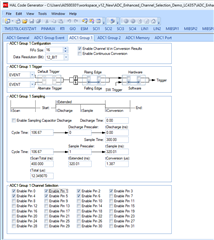
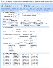
We also explored multiple channel selection in group1, group2 and event group.
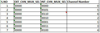
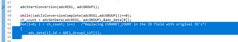
My doubt here is since this channels are converted one after other in sequence, i.e 0,1,2,3,4,...
But we want to have user choice sequence i.e. 0,5,6,2,1,3,4... etc.
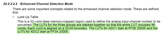
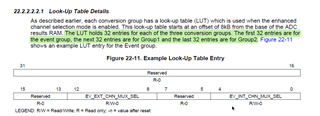
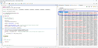
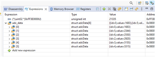
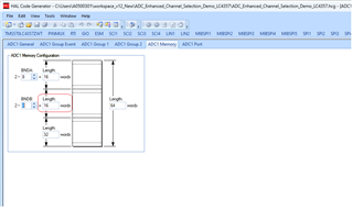
We got to know from TRM that using Enhanced Channel Selection and configuring the LUT it is possible.
Could you please provide some example code on how to do it.
One more doubt using the above feature is it possible to sequence between two group channels like shown in below group
|
Channel seq |
0 | 0 | 1 | 4 | 1 | 5 |
| Group | Grp1 | Grp2 | Grp1 | Grp2 | Grp1 | Grp2 |
Regards,
Pratik