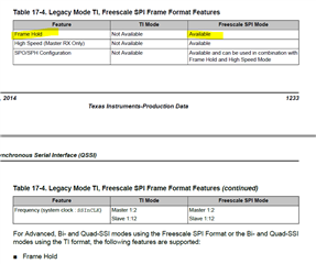
Part Number: TM4C1294NCPDT
Other Parts Discussed in Thread: EK-TM4C1294XL
Hi,
I'm trying to optimize the SPI timing and my goal is to have a continuous clock frame without any pause between bytes.
I use EK-TM4C1294XL to do my tests.
The SSI is configured as a master by using the following function:
SSIConfigSetExpClk(SSI0_BASE, 120000000, SSI_FRF_MOTO_MODE_0, SSI_MODE_MASTER, 1000000, 8);
My component need the SSI_FRF_MOTO_MODE_0 (Idle clock low and capture on first edge of clock)
I use SSI0 and it is configured at 1MHz clock.
To test it after configuration I write to SPI FIFO 4 bytes to be sure to not have any pause between bytes:
HWREG(SPI0_BASE + SSI_O_DR) = 0;
HWREG(SPI0_BASE + SSI_O_DR) = 0;
HWREG(SPI0_BASE + SSI_O_DR) = 0;
HWREG(SPI0_BASE + SSI_O_DR) = 0;
I have a scope plugged on the CLK pin to observe byte stream:
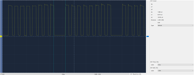
As you can see on the capture, there is a one clock pause between each bytes.
However If I change the format to SSI_FRF_MOTO_MODE_1 or SSI_FRF_MOTO_MODE_3 then there is no pause between every bytes:
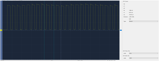
After discovering this I tryed all the mode and it seem that when Phase is 1, then there is a pause of one SPI clock between every bytes:
To resume:
- SSI_FRF_MOTO_MODE_0 and SSI_FRF_MOTO_MODE_2 have a pause between each bytes
- SSI_FRF_MOTO_MODE_1 and SSI_FRF_MOTO_MODE_3 DO NOT have a pause between each bytes
In the documentation it is not specified that there is a pause between every bytes.
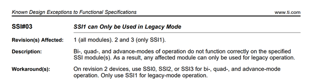
The only part which say that there is a pause is in datasheet at 17.3.8 DMA Operation:
Note: Wait states are inserted at every byte transfer when using Bi- or Quad-SSI modes as a master with the μDMA at SSICLK frequencies greater than 1/6 of the system clock
However I do not use DMA here.
Note I also tryed with DMA and the same behavior is present.
Do you have an idea why there is a 1 SPI clock pause in the stream when Phase is 1?
Regards.