This thread has been locked.

If you have a related question, please click the "Ask a related question" button in the top right corner. The newly created question will be automatically linked to this question.

TMS570LC4357: Multiple communication protocol

Part Number: TMS570LC4357
Other Parts Discussed in Thread: HALCOGEN

Dear  sir ,

I am   trying  to implement  one   logic  for   multiple communication protocol  like  SCI, SPI, I2C , CAN even  RTI  also , all communication should  be  happen  in  single  code,  i will it  possible .

thank you

regards

Jeeva


  • Sir  do you have  any  thread on  I2C  , Iam  working  on example  code  of   I2C  using  Microcontroller  TMS570LC4357 , open drain  connection  external  connection  any details  please share me  sir  it  will really  useful for me , kindly reply me  soon sir 

    Thank  you,

    Regards,

    jeeva

  • what  sir  no reply 

  • Hi Jeev,

    I am   trying  to implement  one   logic  for   multiple communication protocol  like  SCI, SPI, I2C , CAN even  RTI  also , all communication should  be  happen  in  single  code,  i will it  possible .

    Yes, it is possible.

    You just need to combine all the codes in while(1) loop one after another.

    If any peripherals working with interrupts, you just need to add the corresponding code as well.

    Iam  working  on example  code  of   I2C  using  Microcontroller  TMS570LC4357 , open drain  connection  external  connection  any details  please share me  sir  it  will really  useful for me , kindly reply me  soon sir 

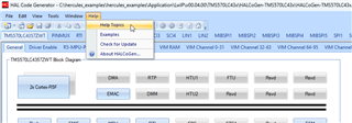
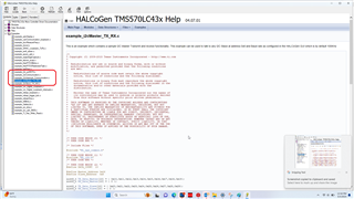
    I2c examples can be found in HALCoGen itself at Help Topics section

    If necessary you can find some more tested examples at below FAQ as well:

    (+) [FAQ] TMS570LC4357: Examples and Demos available for Hercules Controllers (E.g. TMS570x, RM57x and RM46x etc) - Arm-based microcontrollers forum - Arm-based microcontrollers - TI E2E support forums

    --
    Thanks & regards,
    Jagadish.

  • Dear  After  code  and  halcogen   set  ,for  microcontroller(TMS570LC4357)   external full up resistor  should   be required , what will be  value of  resistor . I making  I2C1  as  master  and  I2C2  as  slave  ,that is why  i am asking   external  pull resistor connection  ,  can u give any suggestion related to that  , as  soon as possible 

    thank you 

  • dear sir,

    To  calculate   full  resistor  i am  using   formula   R =  (T_rise)/(2* Total capacitance)   After  referring  data sheets  of  TMS570LS4357   I got  T_rise =  4.2 micro sec,  Total  Capacitance  = 400pf,  after calculation  its  getting  5.875 ohm ,  it   is  correct  sir , reply soon sir    ,.

  • what  sir  no reply 

  • Hi Jeev,

    Please try to use either 2.2K or 2.7K resistors as I2c Pullups.

    Refer below thread to understand more details:

    (+) TMS570LS3137: I2C is not working - Arm-based microcontrollers forum - Arm-based microcontrollers - TI E2E support forums

    --
    Thanks & regards,
    Jagadish.

  • #include "HL_sys_common.h"

    /* USER CODE BEGIN (1) */
    #include "HL_i2c.h"
    /* USER CODE END */

    /** @fn void main(void)
    * @brief Application main function
    * @note This function is empty by default.
    *
    * This function is called after startup.
    * The user can use this function to implement the application.
    */

    /* USER CODE BEGIN (2) */
    #define DATA_COUNT 10U
    #define Master_Address 0x26
    #define Slave_Address 0x8
    uint8_t TX_Data_Master[10] = { 0x10,0x11,0x12,0x13,0x14,0x15,0x16,0x17,0x18,0x19};
    uint8_t RX_Data_Master[10] = { 0 };
    uint8_t TX_Data_Slave[10] = { 0x20,0x21,0x22,0x23,0x24,0x25,0x26,0x27,0x28,0x29};
    uint8_t RX_Data_Slave[10] = { 0 };
    /* USER CODE END */

    int main(void)
    {
    /* USER CODE BEGIN (3) */
    int repeat = 0; int delay =0;
    // Master Transfer Functionality //
    /* I2C Init as per GUI
    * Mode = Master - Transmitter
    * baud rate = 100KHz
    * Count = 10
    * Bit Count = 8bit
    */
    i2cInit();
    /* Configure address of Slave to talk to */
    i2cSetSlaveAdd(i2cREG1, Slave_Address);
    /* Set direction to Transmitter */
    /* Note: Optional - It is done in Init */
    i2cSetDirection(i2cREG1, I2C_TRANSMITTER);
    for(repeat = 0; repeat < 2; repeat++)
    {
    /* Configure Data count */
    /* Note: Optional - It is done in Init, unless user want to change */
    i2cSetCount(i2cREG1, DATA_COUNT);
    /* Set mode as Master */
    i2cSetMode(i2cREG1, I2C_MASTER);
    /* Set Stop after programmed Count */
    i2cSetStop(i2cREG1);
    /* Transmit Start Condition */
    i2cSetStart(i2cREG1);
    /* Tranmit DATA_COUNT number of data in Polling mode */
    i2cSend(i2cREG1, DATA_COUNT, TX_Data_Master);
    /* Wait until Bus Busy is cleared */
    while(i2cIsBusBusy(i2cREG1) == true);
    /* Wait until Stop is detected */
    while(i2cIsStopDetected(i2cREG1) == 0);
    /* Clear the Stop condition */
    i2cClearSCD(i2cREG1);
    /* Simple Dealya before starting Next Block */
    /* Depends on how quick the Slave gets ready */
    for(delay=0;delay<1000000;delay++);
    }
    // Master Receive Functionality //
    /* Configure address of Slave to talk to */
    i2cSetSlaveAdd(i2cREG1, Slave_Address);
    /* Set direction to receiver */
    i2cSetDirection(i2cREG1, I2C_RECEIVER);
    for(repeat = 0; repeat < 2; repeat++)
    {
    /* Configure Data count */
    /* Note: Optional - It is done in Init, unless user want to change */
    i2cSetCount(i2cREG1, DATA_COUNT);
    /* Set mode as Master */
    i2cSetMode(i2cREG1, I2C_MASTER);
    /* Set Stop after programmed Count */
    i2cSetStop(i2cREG1);
    /* Transmit Start Condition */
    i2cSetStart(i2cREG1);
    /* Transmit DATA_COUNT number of data in Polling mode */
    i2cReceive(i2cREG1, DATA_COUNT, RX_Data_Master);
    /* Wait until Bus Busy is cleared */
    while(i2cIsBusBusy(i2cREG1) == true);
    /* Wait until Stop is detected */
    while(i2cIsStopDetected(i2cREG1) == 0);
    /* Clear the Stop condition */
    i2cClearSCD(i2cREG1);
    /* Simple Delay before starting Next Block */
    /* Depends on how quick the Slave gets ready */
    for(delay=0;delay<1000000;delay++);
    }
    }

    this  is  code  i am  using  sir , is  that fine  sir 

  • this  is  code  i am  using  sir , is  that fine  sir 

    The code looks fine.

  • dear   sir ,

    i  have  one  doubt  if  i have  send  through dock light  application  data  in  UART   communication , received  buffer array i  assigned  size as  20  , in   dock light  i want  to send  more that  20 char or  integer  whatever.  it  should  be  send , whatever  i  type  along  with  receiver size  also increase  it  possible sir , if  its  possible  means how  can u explain sir , kindly reply  fast 

    thank you

  • sir   no  reply  i am  with  struct  due  to  above mention  problem , kindly  response   fast

  • Hi Jeev,

    It depends on the baudrate you are using, for example if your baudrate is 9600 then to receive 1byte of data with 2 stop bits then approximately 1msec time will be taken. So, if you are able to process the received data with in below 1ms then you don't get any issues.

    If you are failed to process before 1ms then you will get "Overrun Error", that means the received data might overwrite with newly received data. So, you have to make sure this.

    --
    Thanks & Regards,
    Jagadish.

  • #include "HL_sys_common.h"
    
    
    #include "HL_spi.h"
    #include "HL_sci.h"
    
     void sciDisplayText(sciBASE_t *sci, uint16 *text, uint32 length);
    void spi_func(void);
    #define UART (sciREG1)
    #define SPI1 (spiREG1)
    #define SPI2 (spiREG3)
    #define TX_SIZE 5
        uint16 u16MasterTX_BUF[TX_SIZE] = {0x01,0x02,0x03,0x04,0x05};
       extern uint16  u16MasterRX_BUF[TX_SIZE] = {0};
        uint16 u16SlaveTX_BUF[TX_SIZE] = {0x06,0x07,0x08,0x09,0x0A};
       extern uint16  u16SlaveRX_BUF[TX_SIZE] = {0};
       extern  uint8  u8result1 = 0U;
       extern  uint8  u8result2 = 0U;
    void spi_func(void)
    {
    
        spiInit();
        sciInit();
          spiDAT1_t dataconfig1_t;
    
          dataconfig1_t.CS_HOLD = FALSE;
          dataconfig1_t.WDEL    = TRUE;
          dataconfig1_t.DFSEL   = SPI_FMT_1;
          dataconfig1_t.CSNR    = 0xFE;
    
          if(SPI1== spiREG1)
          {
          spiTransmitAndReceiveData(SPI1, &dataconfig1_t, TX_SIZE, u16MasterTX_BUF, u16SlaveRX_BUF);
          }
          if(SPI2== spiREG3)
          {
            spiTransmitAndReceiveData(SPI2, &dataconfig1_t,TX_SIZE, u16SlaveTX_BUF, u16MasterRX_BUF);
           }
         u8result1 = SpiRxStatus(SPI1);
         u8result2 = SpiRxStatus(SPI2);
    
    }
    int main(void)
    {
    /* USER CODE BEGIN (3) */
        spi_func();
    
        while(1)
            {
              if(u8result1 == 2)
              {
                sciDisplayText(UART, u16MasterRX_BUF, 5U );
              }
              if(u8result2 == 2)
              {
                sciDisplayText(UART, u16SlaveRX_BUF, 5U ) ;
              }
            }
    }
    /* USE
    void sciDisplayText(sciBASE_t *sci, uint16 *text, uint32 length)
    {
        while (length--)
        {
            while ((UART->FLR & 0x4) == 4);
    
                sciSendByte(UART, *text++);
    }
    }
    This  code  i  have  written  for  SPI  using controller TMS570LS4357 , for halcogen iam  little  confuse , what  will be  halcogen setup  sir  and  will this  fine  sir  , modification should done, tell me sir 

  • Hi Jeev,

    It is hard to support all the peripheral issues in one thread. 

    Plese raise a different thread, because in future it is difficult to analyze the threads. Please raise at least one thread for one issue.

    --
    Thanks & regards,
    Jagadish.