This thread has been locked.

If you have a related question, please click the "Ask a related question" button in the top right corner. The newly created question will be automatically linked to this question.

AM2634: GPIO interrupt configurations

Part Number: AM2634
Other Parts Discussed in Thread: TMDSCNCD263, SYSCONFIG,

Dear Team,

I'm using TMDSCNCD263 evaluation board and Gpio interrupt example from SDA, thats working fine, 

Now more interrupt have to configure on GPIO14, GPIO29, GPIO55 and GPIO78, Sysconfig tool used to configure the interrupt on these pins

Initially Pinmux configure as per given example in SDK and same process followed like GPIO_Init()

Now the problem is "How to configure ISR for respective pins?" because I follow the same process as shown i example to configure the ISR in gpio_input_interrupt_main(NULL) function.

I'm using same callback function for all the pins (that should not be the problem)

added code in example to configure the ISR in pins 

HwiP_Params_init(&hwiPrms1);
pinNum = CONFIG_GPIO0_PIN;
hwiPrms1.intNum = intrNum;
hwiPrms1.callback = &GPIO_bankIsrFxn;
hwiPrms1.args = (void *) pinNum;

hwiPrms1.isPulse = TRUE;
retVal = HwiP_construct(&gGpioHwiObject1, &hwiPrms1);


kindly guide whats state forward way to configure ISR  for pins because reading data sheet and configure the ISR is quite complex 

  • Hi Vikas,

    Please refer to the following faq to understand how to Configure GPIO Interrupts in AM263x.
    [FAQ] MCU-PLUS-SDK-AM263X: Configuring GPIO Interrupts

    Regards,
    Akshit

  • I configure the gpio19 in pin interrupt mode 

    and Interrupt enable by 

       HwiP_Params_init(&hwiPrms);
        hwiPrms.intNum = CSLR_R5FSS0_CORE0_CONTROLSS_INTRXBAR0_OUT_19;
        hwiPrms.callback = &GPIO_muxIsrFxn;
        hwiPrms.args = (void *) pinNum;
        retVal = HwiP_construct(&gGpioHwiObject, &hwiPrms);

    call back function isn't hit

    static void GPIO_muxIsrFxn(void *args)
    {
        /*
         * Handle pin interrupt - This is pulse interrupt. No need to clear status
         *
         */
    //    DebugP_log("Interrupt Generated!!\r\n");


        uint32_t    pinNum = (uint32_t) args;
           uint32_t    bankNum =  GPIO_GET_BANK_INDEX(pinNum);
           uint32_t    intrStatus, pinMask = GPIO_GET_BANK_BIT_MASK(pinNum);


           /* Get and clear bank interrupt status */
           intrStatus = GPIO_getBankIntrStatus(gGpioBaseAddr, bankNum);
    //       GPIO_clearBankIntrStatus(gGpioBaseAddr, bankNum, intrStatus);
           gGpioIntrDone2++;
           DebugP_log("Interrupt Generated!!\r\n");
           /* Per pin interrupt handling */

    }

    Can you just cross check what wrong i did

  • Can you try changing  hwiPrms.intNum  to GPIO_INT_XBAR_GPIO_MUX_19, and let me know if it works.

    Thanks
    Akshit

  • GPIO_INT_XBAR_GPIO_MUX_19 is not working for me CSLR_R5FSS0_CORE0_INTR_GPIO_INTRXBAR_OUT_14 is working,

    Am2634 has 144 interrupt enabled gpio So kindly let me know how to configure 20 Pins as interrupts and how to manage call back function for these interrupts?

  • There are only 4 GPIO interrupts mapping to VIM0 then CPU core. The interrupt numbers are 144, 145, 146, and 147.  

    CSLR_R5FSS0_CORE0_INTR_GPIO_INTRXBAR_OUT_14 is --> 144

  • What are the interrupt numbers used for other GPIO interrupt events in your code?

  • As per CSLR_R5FSS0_CORE0_INTR_GPIO_INTRXBAR_OUT_14 142 is interrupt number

    but the question is can we define 20 GPIO interrupts on this MCU/SDK? 

  • Yes, you can define any number of GPIO interrupts in your application. But as mentioned in TRM, there are only 4 VIM channels assigned to all the GPIO interrupts.

    You can have one ISR for GPIO interrupts or up to four ISR for GPIO interrupts.

    1. The interrupt number is 142 if GPIO_INT_XBAR_VIM_MODULE0_0 is selected for XBAR instance 

    2. The interrupt number is 143 if GPIO_INT_XBAR_VIM_MODULE0_1 is selected for XBAR instance 

  • Do you have some sample code for multiple gpio interrupts or let me know how to update the gpio_input_interrupt_am263x-cc_r5fss0-0_nortos_ti-arm-clang project for multiple interrupts 

  • Hi Vikas,

    I don't have a working example for multiple gpio interrupts.

  • Any document to configure multiple GPIO interrupts in AM2634

  • Hi Vikas,

    I am working on a CCS project for handling interrupts from multiple GPIO pins, and will post the project after tested.

  • The following is the GPIO configurations:

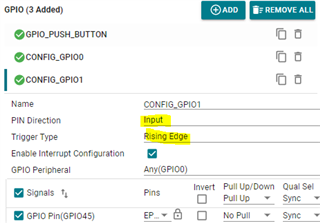
    1. add two more GPIO pins, both are input and triggered at rising edge.

        CONFIG_GPIO0: GPIO43 pin

        CONFIG_GPIO1: GPIO45 pin

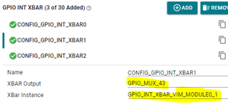
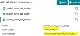
    2. Configure GPIO Interrupt Xbar:

    CONFIG_GPIO0: GPIO43 --> GPIO_INT_XBAR_VIM_MODULE0_1  which is mapped to interrupt number 143

    CONFIG_GPIO0: GPIO45 --> GPIO_INT_XBAR_VIM_MODULE0_3  which is mapped to interrupt number 145

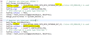
    3. Register pin interrupt for GPIO43 and GPIO45. 

    multiple_gpio_input_interrupt_am263x-cc_r5fss0-0_nortos_ti-arm-clang.zip

  • Thanks Wang and Appreciate your efforts,

    I also try in same way and I able to configure 4 interrupts only, but i need more than 4 interrupts

    because it has 4, GPIO_INT_XBAR_VIM_MODULE0_0/1/2/3 only So can we configure 4 interrupts only? 

    void Drivers_gpioIntXbarOpen()
    {
    /*
    * GPIO INTERRUPT XBAR
    */
    SOC_xbarSelectGpioIntrXbarInputSource(CSL_GPIO_INTR_XBAR_U_BASE, GPIO_INT_XBAR_VIM_MODULE0_0, GPIO_INT_XBAR_GPIO_MUX_21);
    SOC_xbarSelectGpioIntrXbarInputSource(CSL_GPIO_INTR_XBAR_U_BASE, GPIO_INT_XBAR_VIM_MODULE0_1, GPIO_INT_XBAR_GPIO_MUX_43);
    SOC_xbarSelectGpioIntrXbarInputSource(CSL_GPIO_INTR_XBAR_U_BASE, GPIO_INT_XBAR_VIM_MODULE0_3, GPIO_INT_XBAR_GPIO_MUX_45);
    }
     

    In my project I need to use more than 20 GPIO interrupts So please let me know how to configure 20 interrupts,

    I believe Am2634 is most powerful MCU and its has the capability to handle all the GPIO interrupts

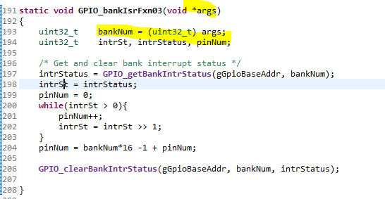
  • You can use GPIO bank interrupt. The 16 GPIO pins in the same bank will share the same interrupt number and interrupt ISR. The IRS can handle the interrupt source by reading the GPIO interrupt status register. 

    I haven't got chance to try, but I think this way should work.

  • 1. Use GPIO bank interrupt 

    You will get an interruption for 16 pins. In the GPIO ISR, you have to check for the interrupt cause for which Pin.

    ISR for GPIO bank interrupt:

    2. Use GPIO individual pin interrupt:

  • Yes, I'm also thinking in a same way and try also, but its not working (This is main problem)

    I configure 5 GPIOs on same bank with same interrupt number, while testing it's giving interrupt  on the last pin not on all pins,

    requesting to test on your side

  • 1. The 5 GPIOs should be in the same GPIO bank

        GPIO[15:0] -- bank 0

        GPIO[31:16] -- bank 1

         etc

    2. XBAR output (GPIO INT BAR) should be the same bank #

    I tested and it works fine.

  • Could you please send the code

  • 7 GPIOs are used in this example. The CONFIG_GPIO2/4/5/6 use the GPIO bank interrupt.

    1. GPIO_Push_Button: GPIO21, GPIO individual pin interrupt, ISR is GPIO_IsrFxn00()

    2. CONFIG_GPIO0: GPIO43,      GPIO individual pin interrupt, ISR is GPIO_IsrFxn01()

    3. CONFIG_GPIO1: GPIO45,      GPIO individual pin interrupt, ISR is GPIO_IsrFxn02()

    4. CONFIG_GPIO2: GPIO49,  GPIO bank interrupt, ISR is GPIO_bankIsrFxn03()

    5. CONFIG_GPIO4: GPIO51,  GPIO bank interrupt, ISR is GPIO_bankIsrFxn03()

    6. CONFIG_GPIO5: GPIO52,  GPIO bank interrupt, ISR is GPIO_bankIsrFxn03()

    7. CONFIG_GPIO6: GPIO55,  GPIO bank interrupt, ISR is GPIO_bankIsrFxn03()


    2311.multiple_gpio_input_interrupt_am263x-cc_r5fss0-0_nortos_ti-arm-clang.zip

  • Great, I found my mistake also

    I passed hwiPrms.args     = pin number instead of bank number while configuring the Bank interrupts