Other Parts Discussed in Thread: TMDSCNCD263, SYSCONFIG,
Dear Team,
I'm using TMDSCNCD263 evaluation board and Gpio interrupt example from SDA, thats working fine,
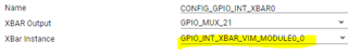
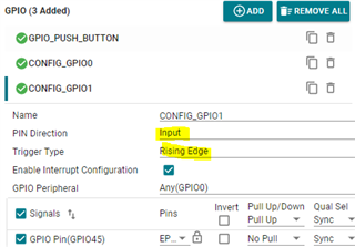
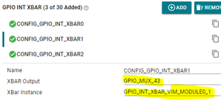
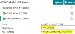
Now more interrupt have to configure on GPIO14, GPIO29, GPIO55 and GPIO78, Sysconfig tool used to configure the interrupt on these pins
Initially Pinmux configure as per given example in SDK and same process followed like GPIO_Init()
Now the problem is "How to configure ISR for respective pins?" because I follow the same process as shown i example to configure the ISR in gpio_input_interrupt_main(NULL) function.
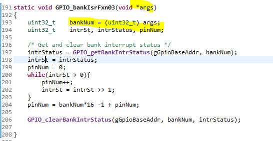
I'm using same callback function for all the pins (that should not be the problem)
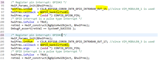
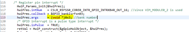
added code in example to configure the ISR in pins
HwiP_Params_init(&hwiPrms1);
pinNum = CONFIG_GPIO0_PIN;
hwiPrms1.intNum = intrNum;
hwiPrms1.callback = &GPIO_bankIsrFxn;
hwiPrms1.args = (void *) pinNum;
hwiPrms1.isPulse = TRUE;
retVal = HwiP_construct(&gGpioHwiObject1, &hwiPrms1);
kindly guide whats state forward way to configure ISR for pins because reading data sheet and configure the ISR is quite complex