Other Parts Discussed in Thread: HALCOGEN
Tool/software:
I think I have trouble configuring SPI to communicate with TPS65381AQDAPRQ1. I believe I have configured everything as it should be but it is not working...
I have placed SPI configuration in _c_int00 function just before call of main() , configuration code looks like this.
    uint32_t i = 3000000;

    for(;i>0;) {
        i--;
    }
    /* Return control and status register values to default */
    mibspiREG2->GCR0 = 0u;

    /* Bring MIBSPI channel out of reset */
    mibspiREG2->GCR0 = 1u;

    /* Data format 0 */
    mibspiREG2->FMT0 = (uint32)((uint32)0U << 24U)                 /* wdelay */
                           | (uint32)((uint32)0U << 23U)                 /* parity Polarity */
                           | (uint32)((uint32)0U << 22U)                 /* parity enable */
                           | (uint32)((uint32)0U << 21U)                 /* wait on enable */
                           | (uint32)((uint32)0U << 20U)                 /* shift direction */
                           | (uint32)((uint32)0U << 17U)       /* clock polarity */
                           | (uint32)((uint32)0U << 16U)          /* clock phase */
                           | (uint32)((uint32)19 << 8U)            /* baudrate prescale - derive SPICLK from VCLK
                                                                            @note: the clock rate (MHz) for data format x can be calculated: VCLK (80MHz) / (PRESCALEx + 1) */
                           | (uint32)((uint32)16U << 0U);                 /* data word length */

    /* Initialize port - set pins as functional */
    mibspiREG2->PC0  = 0u;
    mibspiREG2->PC0  = mibspiREG2->PC0
                           | (uint32)((uint32)1U << 25U)                  /* SOMI[1] */
                           | (uint32)((uint32)1U << 17U)                  /* SIMO[1] */
                           | (uint32)((uint32)1U << 11U)                  /* SOMI[0] */
                           | (uint32)((uint32)1U << 10U)                  /* SIMO[0] */
                           | (uint32)((uint32)1U << 9U)                   /* CLK */
                           | (uint32)((uint32)0U << 8U)                   /* ENA */
                           | (uint32)((uint32)1U << 5U)                   /* SCS[5] */
                           | (uint32)((uint32)1U << 4u)                   /* SCS[4] */
                           | (uint32)((uint32)1U << 3u)                   /* SCS[3] */
                           | (uint32)((uint32)1U << 2u)                   /* SCS[2] */
                           | (uint32)((uint32)1U << 1u)                   /* SCS[1] */
                           | (uint32)((uint32)1U << 0u);                  /* SCS[0] */

    /* Chosen SPI start in master mode */
    mibspiREG2->GCR1 = mibspiREG2->GCR1
                           | (uint32_t)((uint32_t)1U << 24U)               /* SPIEN */
                           | (uint32_t)((uint32_t)0U << 16U)               /* LOOPBACK */
                           | (uint32_t)((uint32_t)0U << 8U)                /* POWERDOWN */
                           | (uint32_t)((uint32_t)1U << 1U)                /* CLKMOD */
                           | (uint32_t)((uint32_t)1U << 0U);               /* MASTER */

    uint8_t chip_select = 0xFD;
    while(((mibspiREG2->BUF) & 0x20000000) != 0u){
                    /* wait for the TXFULL bit to be reset before writing new data to SPIDAT1 register
                     * @note: 0 - transmit buffer is empty, ready to accept a new data
                     *        1 - transmit buffer is full, not ready to accept new data */
                }
    mibspiREG2->DAT1 = ((uint32_t)0U << 28u)
                       | ((uint32_t)63U << 26u)
                       | ((uint32_t)0U << 24u)
                       | ((uint32_t)chip_select << 16u)
                       | ((uint32_t)49152U);

    while(((mibspiREG2->BUF) & 0x80000000u) != 0u){
                    /* wait for the RXEMPTY bit to be reset before reading the SPIBUF register
                     * @note: 0 - new data has been received and copied into RXDATA
                     *        1 - no data has been received since the last read of RXDATA */
                }

    PMIC_VAL = (uint32_t)mibspiREG2->BUF;
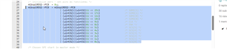
Looking at signals with oscilloscope seems like CS is not working as I thought it will. TPS65381 requires between messages from us to deactivate CS. My understanding was that CS deactivates to default state after every message unless CS_hold was set, which for me is not . Just to note for now SPI is intended to be used in compatibility mode but further down the road we will transition to MiBSPI.
Can you tell me what I might be doing wrong here that I can't communicate properly with TPS65381AQDAPRQ1 .