This thread has been locked.

If you have a related question, please click the "Ask a related question" button in the top right corner. The newly created question will be automatically linked to this question.

AM2732: AM2732 Interrupt Nesting Exception

Part Number: AM2732

Tool/software:

When a low priority IRQ interrupt continues to execute, a high priority interrupt can only be interrupted once

premise:There are only two different priority cycle timers in the system that interrupt IRQ1 and IRQ2, and IRQ1 has a higher priority than IRQ2;

operation:Perform a relatively long delay in IRQ1 to ensure that IRQ2 can be triggered multiple times during the delay period;

Phenomenon: No matter how long the IRQ2 delay event is, IRQ1 can only trigger an interrupt once during the IRQ2 delay period;

This phenomenon does not conform to the conventional understanding of interrupt nesting. If AM2732 has special requirements for this part, please explain. Otherwise, please assist in explaining the cause and solution of this phenomenon. thanks.

  • Hi There,

    Before I answer your questions, I have a few questions for you.

    How did do your experiment?

    What is the hardware platform are you using (AM273x EVM)?

    What version of the MCU+ SDK you are using (09.02.00.52 is the latest one)?

    Are you using FreeRTOS or NORTOS?

    In general, the high priority interrupt can interrupt the low interrupt handling, if the nested interrupt is supported. However, if the high priority ISR is not exited properly (interrupt masking, or without EOI), then the higher priority interrupt may not be properly processed thereafter.

    Best regards,

    Ming

  • Thank you for your answer. I will answer your questions one by one.


    1. I entered a "while (1)" loop in the low priority IRQ2 and did not let IRQ2 exit. I waited for the high priority IRQ1 to interrupt, and used the variable "Irq1_Cnt" to count in the interrupt service function of IRQ1. In the end, I found that the value of Irq1_Cnt was 1; So IRQ1 can interrupt IRQ2, but only once.


    2. The platform I am using is AM273x EVM.


    3&4. I did not use any SDK related code for interrupt handling. We adapted the AUTOSAR OS for this chip, drove interrupts, protected the scene, restored the scene, entered interrupts, confirmed interrupts, and exited interrupts, all of which were implemented by ourselves.


    Attachment: I found that after IRQ1 cannot interrupt IRQ2, when observing the VIM register, the corresponding interrupt displayed in PRIIRQ is IRQ1, and the interrupt displayed in ACTIRQ is IRQ2;
    Note: The interrupt number corresponding to IRQ1 is 109, and the interrupt priority is 2
    The interrupt number corresponding to IRQ2 is 13, and the interrupt priority is 3
    Attached below are corresponding on-site screenshots:https://i.afbcs.cn/vCfGru

  • Hi There,

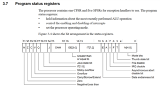
    The first place to check is the I bit of the Program Status Register

    The other register to check is the IRQ mask register. Make sure IRQ1 is not masked

    Please check the value of the following registers:

    #define VIM_STS(j) (0x404U + ((((j) >> 5) & 0xFU) * 0x20U))
    #define VIM_INT_EN(j) (0x408U + ((((j) >> 5) & 0xFU) * 0x20U))
    #define VIM_INT_DIS(j) (0x40CU + ((((j) >> 5) & 0xFU) * 0x20U))

    Best regards,

    Ming

  • Thank you for your reply:
    I have confirmed CPSR The value of I is 0, which belongs to the enable global interrupt state;
    The corresponding registers for high priority IRQ1 (interrupt source 109) are as follows:
    The bit of the VIMsTS register corresponding to IRQ1 is 1 (VIMsTS_3=0x00002000);
    The bit bit of the VIP_EN_SET (VIP_INT_1N) register corresponding to IRQ1 is 1 (VIP_EN_SET_3=0x00002000);
    The bit of the VIP_EN-CLR (VIP_INT-DIS) register corresponding to IRQ1 is 1 (VIP_EN-CLR-3=0x00002000);

  • Hi There,

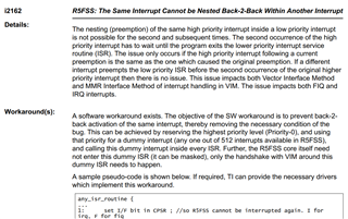
    It is documented in the AM273x errata (www.ti.com/.../swrz101) and a workaround has been provided:

    Best regards,

    Ming

  • I cannot achieve it using the above method,
    Could you please provide the corresponding driver or test routine

  • Hi There,

    When you said "I cannot achieve it using the above method", did you mean you cannoy implement the workaround or the workaround did not work as expected?

    Unfortunately, we do not have the driver and test program for the workaround at hand.

    The idea to workaround the errata is to avoid the back to back of the same interrupt. To achieve this, the dummy a highest priority interrupt by setting the interrupt request register, in every ISR.

    Of course, the easiest thing to do is make sure the IRQ1 is not going to happen more than once in the IRQ2 ISR. You can achieve this by moving the lengthy processing from ISR to a high priority task, so that all ISRs are short and quick. It is always a good practice anyway.

    Best regards,

    Ming 

  • Hello, these days I have been trying to fix the hardware issue using the method described in the AM273x errata manual. However, after testing, we have found that although the original issue has been fixed, it will cause new problems. We have found that there are some interruptions that have not been responded to correctly.

  • Hi There,

    Can you elaborate the "there are some interruptions that have not been responded to correctly" a little bit more.

    Best regards,

    Ming

  • Hello, after completing the interrupt nesting test described above, I caused the system to exit IRQ2. At this time, I found that other interrupt IRQ3 (interrupts with lower priority than IRQ2)  could not receive a normal response. However, before the interrupt nesting test, IRQ3 was able to run normally. I observed the VIM_STS register corresponding to IRQ3 and found that the corresponding bit could not be set properly, but its VIM_EN_SET was successfully set, and the peripheral interrupt flag corresponding to IRQ3 could also be set normally.

  • Hi There,

    The VIM_STS(intNum) is the VIM_RAW(intNum) & VIM_EN(intNum). If you the VIM_STS(intNum) was not set and the VIM_EN(intNum) was set, then the VIM_RAW(intNum) must been cleared. The only place where the VIM_RAW(intNum) may get cleared is in HwiP_clearInt(). Please make sure HwiP_clearInt(IRQ3) never been called in the processing of the IRQ2, IRQ1 and IRQ0 (the highest priority dummy IRQ).

    Best regards,

    Ming

  • Hello:
    I am certain that there is no other way to clear VIM_STS because we are using the RTI module, which triggers a cycle timer interrupt. We found that the RTI counter is running normally, the comparator can also refresh normally, and the interrupt flag bit RTIINTFLAG corresponding to the RTI module can also be set normally, but the interrupt cannot be triggered. We cannot understand the reason for this situation.

  • Hi There,

    Can you share your CCS project and source code, so that we can reproduce the same on our side?

    Best regards,

    Ming 

  • hello  Ming Wei, the source code 《ProgramSC1_20240329_2》already uploaded ,Please check and confirm.AM273x问题复现.pdfAM273x问题复现.docxProgramSC1_20240329_2.zip

  • Hi Currin,

    Thanks a lot for your source code and document. I will test it out on the AM273x EVM and get back to you early next week.

    Best regards,

    Ming 

  • Hi Currin,

    I have tested your code on the AM273x EVM. It does not pass the Os_Init(), therefore Core0_test_App1_Task_5ms_QMCore0_test_App1_Task_10ms_QM are zero.

    After I looked into your code, I saw two issues:

    1.  The way you implemented the workaround for i2162 is questionable. You called the Os_Arch_IrqDummyNest() in the Os_Arch_IrqHandler which is the main IRQ handler. In the Os_Arch_IrqDummyNest(), you set the interrupt flag for dummy IRQ (76), then you cleared it. I am not sure this is the right way to implement the workaround. Here is my understanding about the workaround:

    a. Set the IRQ76 in Os_Arch_IsrUserTable_OsCore_CORE0 to the dummyIrq76Handler in which it will clear the interrupt flag

    b. The set interrupt flag for dummy IRQ (76) in Os_Arch_IrqHandler() which will trigger the IRQ76 and calling to the dummyIrq76Handler

    c. Then the process to the current IRQ (other than IRQ76) will continue.

    2. I do not understand the following staements in Os_Arch_IrqDummyNest():

    /* Get the interrupt vector. */
    irqVecValue = *(volatile uint32*)(OS_ARCH_VIM_BASE_ADDR + OS_ARCH_VIM_IRQVEC);
    /* Write any value to allow the next interrupt. */
    *(volatile uint32*)(OS_ARCH_VIM_BASE_ADDR + OS_ARCH_VIM_IRQVEC) = irqVecValue;

    Best regards,

    Ming

  • hello Ming:
    I will provide the following answers to your doubts.
    1. Our current solution is to strictly follow the Workaround corresponding to the problem (i2162) described in the errata manual provided by TI. Each step can be compared with the solution provided by TI. If you doubt our approach, we hope to receive your driver routine to solve the problem.
    2. Regarding the issue mentioned in "1. abc" above, do you wish to actually trigger the IRQ (76) interrupt and execute the interrupt callback program? However, the solution provided by TI clearly states that the interrupt does not need to enter a specific interrupt callback, and can even be masked.
    3. The question "2" you raised corresponds to steps 3 and 5 in Workaround. If you have any questions, you can read this manual or provide us with corresponding solutions.
    thank you.

  • Hi Renjia,

    I will contact the person who wrote the workaround for this erratum and ask for the test code for this workaround. Will get back to you early next week 

    Best regards,

    Ming

  • Hi Renjia,

    Finally, I was able to run your test program successfully. The reason that I cannot run your test program before was that the AM273x EVM was not initialized properly. I was using C:\ti\mcu_plus_sdk_am273x_09_02_00_52\tools\boot\sbl_prebuilt\am273x-evm\default_sbl_qspi.cfg to flash the QSPI flash. When I change to using the C:\ti\mcu_plus_sdk_am273x_09_02_00_52\tools\boot\sbl_prebuilt\am273x-evm\default_sbl_null.cfg to flash the QSPI flash, boot from flash (to initialize the AM273x SOC, and load your program using CCS, your test program runs properly.

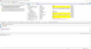
    Screen shot after first pause: 

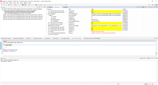
    Screen shot after second pause:

    Both Core0_test_App1_Task_5ms_QM and Core0_test_App1_Task_10ms_QM can continue to count. The OTestStatus is OS_TEST_SUCCESS.

    Please check your SOC initialization. Please refer to the URL for the QSPI flashing details: AM273x MCU+ SDK: Flash a Hello World example (ti.com)

    Best regards,

    Ming

  • hello Ming:
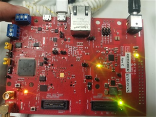
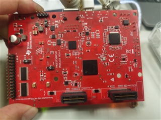
    I used the hardware development board in my hand again for testing, and the phenomenon is still abnormal. Based on your test results, is it possible that the difference is caused by the inconsistency of our hardware? I will take a photo of my hardware and send it to you. I hope you can help me.

    thank you.

  • Hi Renjia,

    I noticed two differences between your EVM and my EVM:

    1. You are using the "No Boot" mode. I am using the QSPI Boot mode. How do you initialize your SOC? (using GEL file?) Please try to use the SBL_NULL with QSPI Boot mode and load your program.

    2. My EVM has the HS-FS device, but yours has the GP device, but I do not think it should cause any issue. I will try the same test on a GP EVM soon.

    Both our EVMs are Rev. C

    Best regards,

    Ming

  • Hi Renjia,

    I tested your application on the AM273x EVM Rev. C with GP device. The result is the same as the HS-FS device. Based on the results, your program should have worked if you use the QSPI boot mode (with SBL_NULL in QSPI flash).

    Best regards,

    Ming


  • Hello Ming:
    Is this issue related to the chip batch

  • Hi Renjia,

    I do not think so. Have you tried the SBL_NULL in QSPI flash and QSPI boot mode?

    Best regards,

    Ming

  • Hello, Ming:
    Sorry, due to personal reasons, I was unable to work properly during this period, so I am only replying to you now. I don't know how to use QSPI boot mode, I hope you can help me. And I'm not sure why different boot modes lead to such a big difference, and can you use no boot mode to help test it.

  • Hi Renjia,

    Please follow the steps described in "SOC Initialization using the Binary Flashed in QSPI memory" section of the following URL:

    AM273x MCU+ SDK: Additional Details

    It describes how to use QSPI boot mode in details.

    Best regards,

    Ming

  • Hi Ming:

        I have successfully downloaded the sbl-NULL file as described in the document.But I couldn't successfully connect to it.Even if the chip is reset, it cannot be connected.What could be the reason.Thanks!

  • Hi Li Geng,

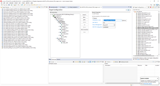
    Please remove all gel file from the CS_DAP_0 of your CCXML file (target configuration file):

    Best regards,

    Ming

  • Hi Ming:

        Thank you for your support. The problem really doesn't arise anymore.But the true cause of the problem is still unclear.NO BOOT mode uses GEL file to boot,and in QSPI boot mode,what is the difference between using the default_sbl_qspi.cfg file and the default_sbl_null.cfg file? What did they do?

  • Hi Geng,

    The No Boot mode is not recommended anyway. It has something to do with the AM273x CSP for CCS.

    The default_sbl_qspi.cfg flashes two images into the QSPI flash, the sbl_qspi and application image, the ROM bootloader (RBL) --> sbl_qspi -->application image, so the application code will run on the R5F cores eventually. Depending on the application image in execution, the R5F cores may not be available for connection. 

    On the other hand, the default_sbl_null.cfg only flashes the sbl_null into the flash, RBL --> sbl_null. Th esbl_null will bring all cores out of the reset and put them in the WFI loop, so that all cores are available for connection.

    Best regards,

    Ming