This thread has been locked.

If you have a related question, please click the "Ask a related question" button in the top right corner. The newly created question will be automatically linked to this question.

MSPM0G3507: Is there a SPI controller example?

Part Number: MSPM0G3507

Tool/software:

Hello,

I am trying to find an example for SPI communication. Only found bsl_spi_flash_interface, in which the SPI is configured as a peripheral instead of controller.

Is there any example for SPI as a controller?

Eventually my question is this. When the MCU is a SPI controller, how will the clock for the slave to respond generated?

In the driverlib API for receiving data from the slave, it doesn't send dummy data to generate the clock.

__STATIC_INLINE uint8_t DL_SPI_receiveData8(SPI_Regs *spi)
{
    return ((uint8_t)(spi->RXDATA));
}

The above API just reads the register.
 
Thanks!
Crane
  • One fairly simple example is spi_controller_multibyte_fifo_poll, here:

    https://dev.ti.com/tirex/explore/node?node=A__ALvL6z3rHe7SZbfM4PrMvA__MSPM0-SDK__a3PaaoK__LATEST

    To (only) receive bytes, you need to transmit that many bytes to trigger the SPI. The example makes it appear you have to transmit something meaningful, but these "dummy" bytes could all be e.g. 0xFF or 0x00 or 0x5A.

  • Thanks Bruce.

    But from the example, I don't see how it receives data after transmitting the data.

    It just calls DL_SPI_receiveDataBlocking8() to receive without transmitting any dummy data. 

        /*
         * Wait to receive the SPI data
         * This loop expects SPI_PACKET_SIZE bytes
         */
        for (uint8_t i = 0; i < SPI_PACKET_SIZE; i++) {
            gRxPacket[i] = DL_SPI_receiveDataBlocking8(SPI_0_INST);
        }

    It might be relevant to the function of the example. 

    Then I looked at another example spi_controller_command_data_control, which is closer to my case.

    But it that example, it only transmits the command, and doesn't receive anything then. I still can't get how the receiving works.

    I tried to submit the dummy data by sending API, and then check the response from the peripherals on the MISO line, but it seems not working for the peripheral to respond with any data.

        CS_ENABLE;
        
        drv_SPI_sendByte(CMD_READ_ID);
        for(i=0; i<9; i++) {
            drv_SPI_sendByte(0); 
            if (DL_SPI_isRXFIFOEmpty(BSL_SPI) == false) {
                drv_SPI_RxData = DL_SPI_receiveData8(BSL_SPI);
                *(data + i) = drv_SPI_RxData;
            }
            else {
                *(data + i) = 0x55;
            }
        }
    
        CS_DISABLE;

    Is this way of receiving correct as both samples don't show that?

    Thanks!

    Crane

  • SPI is intrinsically full-duplex -- for every byte you transmit, you receive one; and, as in this case, if you want to receive a byte you must send one. We refer to "transmit only" and "receive only" transactions, but those only mean that the other end isn't interested in what the data is.

    The example transmits the bytes here:

    >  DL_SPI_fillTXFIFO8(SPI_0_INST, &gTxPacket[0], SPI_PACKET_SIZE);

    >  while (DL_SPI_isBusy(SPI_0_INST));

    Putting a byte into the Tx FIFO causes it to immediately be sent, and the SPI stays busy as long as the Tx FIFO is non-empty. By the end of this sequence, there are 4(=SPI_PACKET_SIZE) bytes already in the Rx FIFO. (It actually doesn't need to use a "Blocking" call to get them.)

    To simplify the example, the author chose a 4-byte transaction, which just fits into the FIFO(s). The code gets a bit more complicated if you want to do more than that. If your drv_SPI_sendByte function waits for completion (DL_SPI_isBusy is fine, or you could use DL_SPI_receiveDataBlocking8) I would expect the Rx FIFO check to always say non-empty.

  • For example, the L6470 SPI stepper motor controller uses NOP bytes to receive multi-byte responses after a single byte request for information command:

  • Thanks Bruce and Keith.

    I do receive one more byte, but all received data are 0.

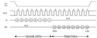
    But the major issue now is that I need CS signal like this:

    By submitting dummy data, I do get the clock to receive the response, but I also got the inconsecutive CS signal between each byte like this. This makes the peripheral in a state of always waiting for the command. I guess this is the reason why I get only 0.

    How to generate the clock for the peripheral to respond and keep the CS signal active at the same time?

    Then from the example, I see that the inconsecutive CS exists for multiple-byte submission as well. But the peripheral needs the CS during the submission of command like this:

    How to achieve this?

    Thanks!

    Crane

  • It looks only 3-wire mode would work to achieve this CS.

    Would 4-wire mode work?

    Thanks!

    Crane

  • Yes, I recommend using 3-wire mode and generating CS using a GPIO (the GPIO you choose could be the one that the SPI unit would use in 4-wire mode, if you don't want to re-wire). The code snippet you posted seems to be doing the right thing.

    Just to be clear: that first (command) byte will result in a receive byte, which you'll need to read and discard.

  • Ok got it. 

    To receive this byte from submitting the command is to clear RxFIFO not-empty status or clear the data buffer, or together? In the spec, I don't see the description about how the status is updated and how data buffer is updated.

  • Just read the receive byte and throw it away. Maybe something like:

      CS_ENABLE;
      DL_SPI_transmitDataBlocking8(SPI_0_INST, command);
      (void)DL_SPI_receiveDataBlocking8(SPI_0_INST); // Read and throw away 
      DL_SPI_transmitDataBlocking8(SPI_0_INST, 0x5A); // Dummy write (0x5a looks good on a scope)
      response = DL_SPI_receiveDataBlocking8(SPI_0_INST); // Read the result
      CS_DISABLE;

  • Yes understand.

    Try to understand what's behind so as to know how to read and discard when the command has multiple bytes (sequence and the quantity).

    Eventually found that it works to read and discard the same number of bytes as submitted in command right after the command is sent. I guess this is the way it works.

  • Yes, for a e.g. 3-byte "command" you would (probably) throw away the first 3 receive bytes. The model I suggested doesn't use the FIFO very well, but for a short transaction that doesn't matter much. (For a long transaction you should consider DMA.)

    [That "(probably)" is where those waveforms come in. The first one you posted shows a flatline on Rx during the first Tx byte, but that's actually an Rx byte, just not an interesting one. Similarly during the second byte the Tx is shown as flatlined, but that's the dummy Tx byte (it's not really "Hi-Z", but it might as well be). For a multi-byte command, it's (theoretically) possible the target would start sending the result before the command is complete, in which case the waveform in its datasheet would reflect that.]

  • Yes, you are right. Those flatline which shows "Hi-Z" should be either dummy for SI or something coming from the peripheral on SO. It is confusing to put "Hi-Z" there. 

    I am done with this question. Thanks Bruce for your help!

    Crane