Part Number: AM263P4
Other Parts Discussed in Thread: DP83826E, SYSCONFIG
Tool/software:
I am trying to bring-up CPSW with a DP83826E on a custom PCB.
So far, I have been able to bind a driver, but I have not been able to successfully establish Link Status.
The CPSW driver is configuring the PHY, and then entering FSM state ENETPHY_FSM_STATE_NWAY_WAIT.
This eventually results in EnetPhy_phyTimeout() and FSM state ENETPHY_FSM_STATE_FOUND. The process configuration, and Auto Negotiation wait then repeats.
I added some DebugP_log() printfs to aid troubleshooting. These print BMCR,BMSR: registers from within enetphy.c. These printfs are in hexadecimal, and can be seen here:
[Cortex_R5_1] ==========================
CPSW LWIP TCP CLIENT
==========================
u32IdRead:10,10,0
Starting lwIP.Enet IF UP Event. Local interface IP:192.168.1.253
Waiting for network UP ...
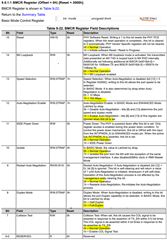
BMCR,BMSR:3100,7849
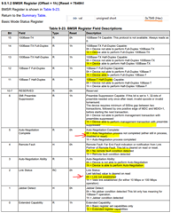
BMSR:7849
BMSR:7849
BMSR:7849
BMSR:7849
BMSR:7849
BMSR:7849
BMSR:7849
BMSR:7849
BMSR:7849
BMSR:7849
BMSR:7849
BMSR:7849
BMSR:7849
BMSR:7849
BMSR:7849
BMSR:7849
Waiting for network UP ...
BMSR:7849
BMSR:7849
BMSR:7849
BMSR:7849
BMSR:7849
Note: The print:
u32IdRead:10,10,0
means the PHYIDR1, PHYIDR2 registers have been successfully read 10 times, and each time the values matched what is specified in the DP83826 datasheet.
I have tried linking with link partners:
TL-SG105 – simple switch
Windows PC - computer
Both link partners have been used successfully for numerous other Ethernet tests. I also tried swapping Cat6 Ethernet cables. These cables also are ‘known good’.
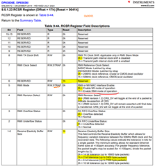
For reference, I decoded the BMCR and BMSR registers.
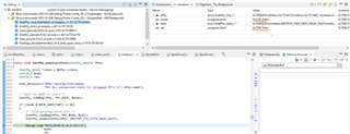
This is the debug view when halted at EnetPhy_nwayStartState() :
Q1a:
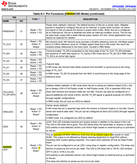
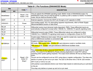
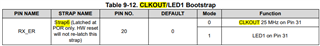
Am I missing something in the PHY configuration?
Q1b:
Are there any other registers that would be useful to analyze?
Q2:
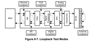
I am considering adding Loopback test functionality to my project. Do you think an analog loopback would be an efficient way to troubleshoot?
Q3:
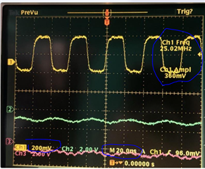
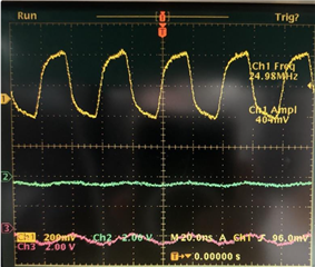
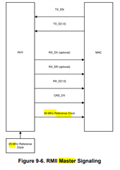
I am considering probing on MDI to see if there is Autonegotiation occurring. My scope may not be able to decode the signals TD+ TD- RD+ RD- signals, but I believe I should be able to detect if there are transmissions occurring.
Is probing MDI useful for troubleshooting?
Q4:
Can you recommend any other troubleshooting measures not mentioned here?