This thread has been locked.

If you have a related question, please click the "Ask a related question" button in the top right corner. The newly created question will be automatically linked to this question.

AM2634: SBL qspi boot

Part Number: AM2634
Other Parts Discussed in Thread: UNIFLASH, , LP-AM263

Tool/software:

I am having issues booting the default sbl_qspi.release.tiimage SBL image from the SDK in either QSPI (4S) or QSPI (1S) mode on my custom board.

I can run the QSPI tests built on CCS using JTAG ok.

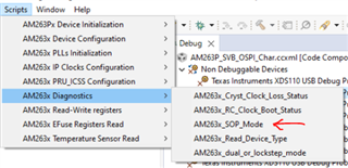
I program the flash using uart_uniflash.py and default sbl_qspi image with switch settings for UART boot SOP0=0, SOP1=1, SOP2=1, SOP3=1 but when I change the switch settings to SOP0=1, SOP1=0, SOP2=1, SOP3=1 (QSPI (1S)) and power cycle I do not see "Starting QSPI Bootloader ..." on the console of my PC. However with my scope I can see activity on the clock and data line into micro at boot from the flash device.

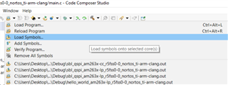
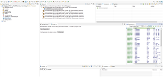
(1) Tests loaded using JTAG using custom board with -

Processor = AM2634COKFHMZCZRQ1
SDK = mcu_plus_sdk_am263x_09_02_00_55
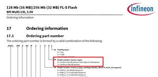
Flash = S25FL128SAGNFI010
CCS = 12.7.1.00001

[Cortex_R5_0] [QSPI Flash Diagnostic Test] Starting ...
[QSPI Flash Diagnostic Test] Flash Manufacturer ID : 0x1
[QSPI Flash Diagnostic Test] Flash Device ID       : 0x2018
[QSPI Flash Diagnostic Test] Executing Flash Erase on first block...
[QSPI Flash Diagnostic Test] Done !!!
[QSPI Flash Diagnostic Test] Performing Write-Read Test...
[QSPI Flash Diagnostic Test] Write-Read Test Passed!
[QSPI Flash Diagnostic Test] Error in reading SFDP Table or SFDP not supported by Flash !!!
All tests have passed!!


[Cortex_R5_0] [QSPI Flash Transfer Test] Starting ...
[QSPI Flash Transfer Test] Executing Flash Erase on first block...
[QSPI Flash Transfer Test] Performing Write-Read Test...
All tests have passed!!

(2) Flashing default sbl_qspi.release.tiimage from SDK prebuilt. Flash and verification OK, but nothing on console when power cycle with switch settings on QSPI (1S) boot or QSPI (4S). I was expecting "Starting QSPI Bootloader ...".

c:\ti\mcu_plus_sdk_am263x_09_02_00_55\tools\boot>python uart_uniflash.py -p COM11 --cfg=default_sbl_qspi.cfg

Parsing config file ...
Parsing config file ... SUCCESS. Found 2 command(s) !!!

Executing command 1 of 2 ...
Found flash writer ... sending sbl_prebuilt/am263x-lp/sbl_uart_uniflash.release.tiimage
Sent flashwriter sbl_prebuilt/am263x-lp/sbl_uart_uniflash.release.tiimage of size 42129 bytes in 4.0s.

Executing command 2 of 2 ...
Command arguments : --file=sbl_prebuilt/am263x-lp/sbl_qspi.release.tiimage --operation=flash --flash-offset=0x0
Sent sbl_prebuilt/am263x-lp/sbl_qspi.release.tiimage of size 227181 bytes in 24.05s.
[STATUS] SUCCESS !!!

All commands from config file are executed !!!

  • Hi Douglas Bolton,

    Thank you for the query!

    Can you please ensure that SOP pins set the custom board to correct/required bootmode?

    Please follow the below steps for checking the SOP mode:

    1. Create a ccxl with AM263x GEL file path(device_gel path) in Target configuration-> CS_DAP_0.
    2. Launch the newly created ccxml file.
    3. Connect to DAP.
    4. Connect to Cortex_R50.
    5. Go to Scripts tab -> AM263x Diagnostics -> AM263x_SOP_Mode


    Best Regards,
    Rijohn

  • Thank you for the quick answer Rijohn.

    I followed your instructions and the reading of my SOP switches is correct.

    Cortex_R5_0: GEL Output:

     ***All IP Clocks are Enabled***

    Cortex_R5_0: AM2634
    Cortex_R5_0: GEL Output: SOP MODE = 0x00000005    
    Cortex_R5_0: GEL Output:
     QSPI - 1S Fallback UART boot mode

    I ordered and received yesterday an LP-AM263 Launchpad. Booting from flash works OK with the launchpad, but not from my custom pcb.

    Studying the schematics I think my issue could the lack of a tri-state buffer between the SOP switch selection and the micro/devices on my custom pcb.

    The extra speed/different setup of the RBL ROM code is probably the difference between running the diag/transfer tests and the RBL code.

    Today I am going to try and hack a buffer onto by custom board and see if it fixes the issue.

    Thanks.

  • Hi Rijohn,

    I managed to put a tri-state buffer on the SOP pins on my custom pcb and I checked the pin state using JTAG and your instructions and all was OK. However, I am still getting the same issues of diag/transfer tests OK but RBL boot from flash not working. Everything works OK on the LP-AM263 board.

    I then compared  the actual devices on the LP-AM263 and my custom pcb -

    LP-AM263 -
    S25FL128SAGNFI000

    Custom pcb -
    S25FL128SAGNFI010

    Looking at the datasheet the difference appears to be -


    Could this difference be the issue why the RBL ROM code does not boot?

    Thank you

    Douglas.

  • Hi Douglas,

    Can you please do the following steps and see where the Program counter is:

    1. Import sbl_qspi_am263x-lp_r5fss0-0_nortos_ti-arm-clang project in <mcu_plus_sdk> to CCS.
    2. Set the board SOP pins to QSPI - 1S Fallback UART boot mode.
    3. Create and launch a new ccxml file with NO Gels in DAP and CORE.
    4. Connect to DAP and Core
    5. Load symbols of this project ( sbl_qspi_am263x-lp_r5fss0-0_nortos_ti-arm-clang)
    6. See where is the Program Counter.

    Regards,
    Rijohn

  • Rijohn, do you know if the different S25FL128 sector sizes could be the issue?

    Could be the uniflash programmer or the RBL code not matching the flash architecture?

    If so I will re-spin the board with the tri-state buffer on SOP pins and exactly the same part number as the LP-AM263.


  • Hi Douglas,

    Sorry for the delay.

    Rijohn, do you know if the different S25FL128 sector sizes could be the issue?

    This will not affect it.

    Custom PCB should ensure the proper Power-On and Reset Sequencing as mentioned section 7.11.2.1 in AM263-datasheet. LP-AM263 uses SN74AVC4T245RSVR as  the tri-sate buffer.

    Can you please confirm the following:
    1) Are a you able to to see 'C' character printed in a serial port (baud rate = 115200) once boot mode set to UART.
    2) Added a loop_forever() function in the SBL_QSPI project (C:\ti\mcu_plus_sdk_am263x_09_02_00_56\examples\drivers\boot\sbl_qspi\am263x-lp) and follow the steps in this e2e to step in and see exactly where program is getting halted.

    Best Regards,
    Rijohn 

  • 1) Are a you able to to see 'C' character printed in a serial port (baud rate = 115200) once boot mode set to UART.

    Yes

    2) Added a loop_forever() function in the SBL_QSPI project (C:\ti\mcu_plus_sdk_am263x_09_02_00_56\examples\drivers\boot\sbl_qspi\am263x-lp) and follow the steps in this e2e to step in and see exactly where program is getting halted.

    This worked OK for the TI Launchpad board and I could step around the infinite loop in assembler -


    On my custom board Uniflash programmed and verified OK but character 'C' was printed on serial port (UART fallback) and program counter was wrong -


    I have added a buffer to the SOP pins and I am getting another pcb manufactured -


  • Hi Douglas,


    I have added a buffer to the SOP pins and I am getting another pcb manufactured

    From my understanding, this should resolve this problem.

    Please refer to this e2e  for more insights regarding "Buffer on SOP boot mode pins"

    Best Regards,
    Rijohn

  • Thank you.

    I will test on the new pcb and see if this resolves the issue.