This thread has been locked.

If you have a related question, please click the "Ask a related question" button in the top right corner. The newly created question will be automatically linked to this question.

MSPM0G3507: ADC noise issue, It seems to be related to Sample Clock Divider and CPUCLK

Part Number: MSPM0G3507

Tool/software:

Hi,

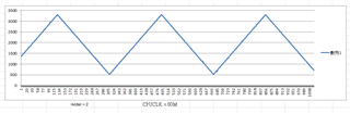
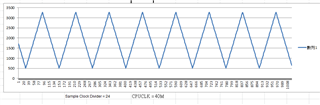
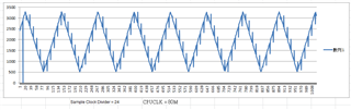
When I was using the ADC to collect values, something happened: When Sample Clock Divider = 1 or 2, everything looked normal. But when Sample Clock Divider = 24, I received some noise, and the normal picture was The abnormal picture is below. There is an interesting thing at the same time. If I reduce the CPUCLK to 40M, no matter what the Sample Clock Divider is, it will be normal. What is the reason? How can I take into account both CPUCLK = 80M and Sample Clock Divider = 24? ? The ADC Clock Source is ULPCLK

Thanks for your help

  • Hi,

    Could you provide your test code with this issue you observed? We can take a look into it and check what could be wrong about it. 

    Best regards,

    Cash Hao

  • Hi Cash Hao,

    Thanks, I import "adc12_triggered_by_timer_event_LP_MSPM0G3507_nortos_ticlang" from mspm0_SDK.

    Below are the changes I made
    1. Add UART for print (UART0, Baud Rate : 115200)

    2.Clock tree : Enable HFXT(40M), select XTAL, Select HFCLK, set QDIV to x4,  select SYSPLL0, set  UDIV to /2

    3. in ADC12, change ADC clock source to ULPCLK, set Sample Clock Divider to Divide by 24, set Reference Voltage to VREF

    4. Enable VREF, mode set to External, VREF+- enabled and External voltage set to 1.5

    FB

    /*
     * Copyright (c) 2021, Texas Instruments Incorporated
     * All rights reserved.
     *
     * Redistribution and use in source and binary forms, with or without
     * modification, are permitted provided that the following conditions
     * are met:
     *
     * *  Redistributions of source code must retain the above copyright
     *    notice, this list of conditions and the following disclaimer.
     *
     * *  Redistributions in binary form must reproduce the above copyright
     *    notice, this list of conditions and the following disclaimer in the
     *    documentation and/or other materials provided with the distribution.
     *
     * *  Neither the name of Texas Instruments Incorporated nor the names of
     *    its contributors may be used to endorse or promote products derived
     *    from this software without specific prior written permission.
     *
     * THIS SOFTWARE IS PROVIDED BY THE COPYRIGHT HOLDERS AND CONTRIBUTORS "AS IS"
     * AND ANY EXPRESS OR IMPLIED WARRANTIES, INCLUDING, BUT NOT LIMITED TO,
     * THE IMPLIED WARRANTIES OF MERCHANTABILITY AND FITNESS FOR A PARTICULAR
     * PURPOSE ARE DISCLAIMED. IN NO EVENT SHALL THE COPYRIGHT OWNER OR
     * CONTRIBUTORS BE LIABLE FOR ANY DIRECT, INDIRECT, INCIDENTAL, SPECIAL,
     * EXEMPLARY, OR CONSEQUENTIAL DAMAGES (INCLUDING, BUT NOT LIMITED TO,
     * PROCUREMENT OF SUBSTITUTE GOODS OR SERVICES; LOSS OF USE, DATA, OR PROFITS;
     * OR BUSINESS INTERRUPTION) HOWEVER CAUSED AND ON ANY THEORY OF LIABILITY,
     * WHETHER IN CONTRACT, STRICT LIABILITY, OR TORT (INCLUDING NEGLIGENCE OR
     * OTHERWISE) ARISING IN ANY WAY OUT OF THE USE OF THIS SOFTWARE,
     * EVEN IF ADVISED OF THE POSSIBILITY OF SUCH DAMAGE.
     */
    
    #include "ti_msp_dl_config.h"
    
    #define ADC_SAMPLE_SIZE (1024)
    /* When FIFO is enabled 2 samples are compacted in a single word */
    #define ADC_FIFO_SAMPLES (ADC_SAMPLE_SIZE >> 1)
    
    uint16_t gADCSamples[ADC_SAMPLE_SIZE];
    volatile bool gCheckADC;
    
    void SendString(char *String, int Length)
    {
        int i;
        for(i = 0 ;i < Length ; i++)
        {
            DL_UART_Main_transmitData(UART_0_INST, String[i]);
            delay_cycles(8000);
        }
    
    }
    
    int main(void)
    {
        char Data[100];
        int i;
        SYSCFG_DL_init();
    
        /* Configure DMA source, destination and size */
        DL_DMA_setSrcAddr(DMA, DMA_CH0_CHAN_ID,
            (uint32_t) DL_ADC12_getFIFOAddress(ADC12_0_INST));
    
        DL_DMA_setDestAddr(DMA, DMA_CH0_CHAN_ID, (uint32_t) &gADCSamples[0]);
        DL_DMA_setTransferSize(DMA, DMA_CH0_CHAN_ID, ADC_FIFO_SAMPLES);
    
        DL_DMA_enableChannel(DMA, DMA_CH0_CHAN_ID);
    
        /* Setup interrupts on device */
        NVIC_EnableIRQ(ADC12_0_INST_INT_IRQN);
    
        gCheckADC = false;
    
        DL_ADC12_startConversion(ADC12_0_INST);
    
    // for test ADC noise
        while (false == gCheckADC) {
            __WFE();
        }
    
        DL_ADC12_stopConversion(ADC12_0_INST);
        DL_DMA_disableChannel(DMA, DMA_CH0_CHAN_ID);
    
        for(i=0;i<ADC_SAMPLE_SIZE;i++)
        {
            sprintf(Data,"%04d\n",gADCSamples[i]);
            SendString(Data,5);
        }
    
    // end
        __BKPT(0);
    
        while (1) {
            __WFI();
        }
    }
    
    void ADC12_0_INST_IRQHandler(void)
    {
        switch (DL_ADC12_getPendingInterrupt(ADC12_0_INST)) {
            case DL_ADC12_IIDX_DMA_DONE:
                gCheckADC = true;
                break;
            default:
                break;
        }
    }
    
    /**
     * These arguments were used when this file was generated. They will be automatically applied on subsequent loads
     * via the GUI or CLI. Run CLI with '--help' for additional information on how to override these arguments.
     * @cliArgs --device "MSPM0G350X" --package "LQFP-64(PM)" --part "Default" --product "mspm0_sdk@2.00.01.00"
     * @versions {"tool":"1.20.0+3587"}
     */
    
    /**
     * Import the modules used in this configuration.
     */
    const ADC12  = scripting.addModule("/ti/driverlib/ADC12", {}, false);
    const ADC121 = ADC12.addInstance();
    const Board  = scripting.addModule("/ti/driverlib/Board");
    const SYSCTL = scripting.addModule("/ti/driverlib/SYSCTL");
    const UART   = scripting.addModule("/ti/driverlib/UART", {}, false);
    const UART1  = UART.addInstance();
    const VREF   = scripting.addModule("/ti/driverlib/VREF");
    
    /**
     * Write custom configuration values to the imported modules.
     */
    const divider9       = system.clockTree["UDIV"];
    divider9.divideValue = 2;
    
    const multiplier2         = system.clockTree["PLL_QDIV"];
    multiplier2.multiplyValue = 4;
    
    const mux4       = system.clockTree["EXHFMUX"];
    mux4.inputSelect = "EXHFMUX_XTAL";
    
    const mux8       = system.clockTree["HSCLKMUX"];
    mux8.inputSelect = "HSCLKMUX_SYSPLL0";
    
    const mux12       = system.clockTree["SYSPLLMUX"];
    mux12.inputSelect = "zSYSPLLMUX_HFCLK";
    
    const pinFunction4       = system.clockTree["HFXT"];
    pinFunction4.enable      = true;
    pinFunction4.inputFreq   = 40;
    pinFunction4.HFXTStartup = 100;
    
    ADC121.$name                          = "ADC12_0";
    ADC121.repeatMode                     = true;
    ADC121.adcMem0chansel                 = "DL_ADC12_INPUT_CHAN_4";
    ADC121.sampleTime0                    = "62.5 ns";
    ADC121.powerDownMode                  = "DL_ADC12_POWER_DOWN_MODE_MANUAL";
    ADC121.enableFIFO                     = true;
    ADC121.configureDMA                   = true;
    ADC121.sampCnt                        = 6;
    ADC121.enabledDMATriggers             = ["DL_ADC12_DMA_MEM10_RESULT_LOADED"];
    ADC121.enabledInterrupts              = ["DL_ADC12_INTERRUPT_DMA_DONE"];
    ADC121.adcMem0vref                    = "VREF";
    ADC121.sampClkSrc                     = "DL_ADC12_CLOCK_ULPCLK";
    ADC121.sampClkDiv                     = "DL_ADC12_CLOCK_DIVIDE_24";
    ADC121.peripheral.$assign             = "ADC0";
    ADC121.peripheral.adcPin4.$assign     = "PB25";
    ADC121.adcPin4Config.$name            = "ti_driverlib_gpio_GPIOPinGeneric0";
    ADC121.DMA_CHANNEL.$name              = "DMA_CH0";
    ADC121.DMA_CHANNEL.addressMode        = "f2b";
    ADC121.DMA_CHANNEL.peripheral.$assign = "DMA_CH0";
    
    
    SYSCTL.forceDefaultClkConfig = true;
    SYSCTL.clockTreeEn           = true;
    
    UART1.$name                            = "UART_0";
    UART1.targetBaudRate                   = 115200;
    UART1.peripheral.rxPin.$assign         = "PA11";
    UART1.peripheral.txPin.$assign         = "PA10";
    UART1.txPinConfig.$name                = "ti_driverlib_gpio_GPIOPinGeneric3";
    UART1.txPinConfig.direction            = scripting.forceWrite("OUTPUT");
    UART1.txPinConfig.hideOutputInversion  = scripting.forceWrite(false);
    UART1.txPinConfig.onlyInternalResistor = scripting.forceWrite(false);
    UART1.txPinConfig.passedPeripheralType = scripting.forceWrite("Digital");
    UART1.rxPinConfig.$name                = "ti_driverlib_gpio_GPIOPinGeneric4";
    UART1.rxPinConfig.hideOutputInversion  = scripting.forceWrite(false);
    UART1.rxPinConfig.onlyInternalResistor = scripting.forceWrite(false);
    UART1.rxPinConfig.passedPeripheralType = scripting.forceWrite("Digital");
    
    VREF.basicVrefPins          = "VREF+-";
    VREF.basicMode              = "DL_VREF_ENABLE_DISABLE";
    VREF.basicExtVolt           = 1.5;
    VREF.vrefPosPinConfig.$name = "ti_driverlib_gpio_GPIOPinGeneric1";
    VREF.vrefNegPinConfig.$name = "ti_driverlib_gpio_GPIOPinGeneric2";
    
    /**
     * Pinmux solution for unlocked pins/peripherals. This ensures that minor changes to the automatic solver in a future
     * version of the tool will not impact the pinmux you originally saw.  These lines can be completely deleted in order to
     * re-solve from scratch.
     */
    pinFunction4.peripheral.$suggestSolution           = "SYSCTL";
    pinFunction4.peripheral.hfxInPin.$suggestSolution  = "PA5";
    pinFunction4.peripheral.hfxOutPin.$suggestSolution = "PA6";
    Board.peripheral.$suggestSolution                  = "DEBUGSS";
    Board.peripheral.swclkPin.$suggestSolution         = "PA20";
    Board.peripheral.swdioPin.$suggestSolution         = "PA19";
    UART1.peripheral.$suggestSolution                  = "UART0";
    VREF.peripheral.$suggestSolution                   = "VREF";
    VREF.peripheral.vrefPosPin.$suggestSolution        = "PA23";
    VREF.peripheral.vrefNegPin.$suggestSolution        = "PA21";
    

  • Hi,

    Which SDK version you are using? 

    It would be much preferred if you can go to your CCS workspace and compress your project file and send it here. 

    Best regards,

    Cash Hao

  • Err80M.zip

    Hi Cash,

    FYI, and this file is modify from "mspm0_sdk_2_00_01_00" "adc12_max_freq_dma_LP_MSPM0G3507_nortos_ticlang"

    In addition, I did some verification today. Since the error is fixed to occur every 12 transactions and the wrong value, I tried to set "Enable DMA Triggers" from MEM10 to MEM11. This error will not exist. Is there a reasonable explanation?

  • Hi,

    It should not related to that e2e issue. 

    In your DMA configuration, the source length is Word(4 bytes). One ADC result is 2 bytes. So, the DMA move 2 ADC results in one time. And DMA Samples Count is 6. So, DMA will move 6*2 = 12 ADC results in a row. 

    Since your DMA trigger is MEM10, it only contains 11 ADC results. Due to DMA will move 12 ADC results in a row. And the ADC result saved in the MEMRESx register is in FIFO mode. The DMA will move (11 new ADC result and 1 previous ADC result). That is why you seen this issue. 

    Best regards,

    Cash Hao

  • Hi Cash,

    Thank you for your explanation! I understand!

    FB

  • Hi Keith,

    Thanks! This helps me a lot! Thank you!

    FB