This thread has been locked.

If you have a related question, please click the "Ask a related question" button in the top right corner. The newly created question will be automatically linked to this question.

MSPM0G3507: ADC DMA Samples Count

Part Number: MSPM0G3507
Other Parts Discussed in Thread: , MSPM0G3107

Tool/software:

Hello Technical Support,

I am working on an application with the MSPM0G3507 microcontroller, where an analog signal needs to be sampled very quickly (in the microsecond range) and reconstructed as accurately as possible. While I am currently using the LP-MSPM0G3507 for this purpose, it will be replaced by the MSPM0G3107 in the final project. However, I have encountered a few obstacles and hope to receive some assistance here.

Depending on the selected DMA sample count (referred to as SAMPCNT in the manual), the output image varies significantly. For visualization, I have applied a 50 Hz sine wave signal with an amplitude of 1 V and an offset of 1.65 V to an ADC. The sampling time used is 20 µs. After the measurement, I reconstruct the signal by multiplying each index by the sampling time. To obtain all these results, I used the example project adc12_max_freq_dma and only changed the input channel, the sampling time, and the DMA samples count.


I have also observed changes in the runtimes for the measured values.


The value 6 appears to be the best for this sampling time. However, when I use 2 µs instead of 20 µs, the value 7 seems to be the best choice, although there is still a small deviation.


I also tested 11 µs, but none of the values seem to fit well.


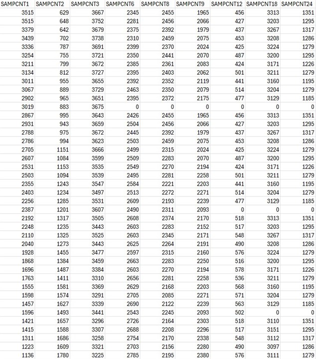
Another anomaly I noticed is that 12 measured values are already transferred from SAMPCNT 6 onwards. This is apparent from the '0', which is due to the default use of DL_ADC12_DMA_MEM10_RESULT_LOADED in the project, instead of DL_ADC12_DMA_MEM11_RESULT_LOADED as in other projects. Repetitions can be detected starting from SAMPCNT 8. I would understand this from SAMPCNT 13 onwards, given that the microcontroller only has 12 conversion-result storage registers. For reference, you can see the first measured values received from the test with a 20 µs sampling time.


I would appreciate any guidance or suggestions you can provide to help resolve these issues.

Important informations:
Code Composer Studio Version:
12.7.0.00007
MSPM0 SDK Version:
2.01.00.03
MSPM0G3507 Version:
2h
MSPM0G3507 Partnum:
BB88h

Kind Regards

  • Hi Alex,

    I would suggest keeping the sample count of the DMA the same and increasing the DMA trigger enable from "MEM10 result Loaded interrupt" to MEM11 result Loaded interrupt if you are going to keep the sample time of 20us. The DMA is way faster than the ADC that is why initially, the DMA enable is triggered after the ADC FIFO gets its 10th Value because by the time the DMA is finished transferring the first 11 values from the ADC FIFO, the 12th value will already be in the ADC FIFO and the DMA will transfer that last value. In your case when you slow the ADC down to 20us, the DMA will transfer the first 11 ADC FIFO values faster than the 12th ADC sample can get into the ADC FIFO. Thus, the DMA will end up grabbing MEMres11 (12th value) before its ready.

  • Dear Fabrice,

    thank you for your reply.

    I require a sampling rate of 1.5 µs. The 20 µs figure originates from my initial collection of 1024 samples, which enables me to analyse a complete period.

    The challenge arises when I need to choose between "MEM10 result Loaded interrupt" and "MEM11 result Loaded interrupt." The manual indicates that SAMPCNT refers to the "Number of ADC converted samples to be transferred on a DMA trigger." Therefore, it should ideally transfer 6 values. However, as illustrated in the table on line 12, due to the presence of 0, a total of 12 values are being transferred.

    Initially, I modified only the sample time but was unable to successfully reconstruct the signal. Upon realizing that SAMPCNT seemingly affects the sampling time, I made adjustments over the past two days, which ultimately allowed me to reconstruct the signal. The only potential issue is that if I switch from the launchpad to the individual microcontroller, a different combination might yield better results, although I cannot clarify why this discrepancy occurs.

    To successfully reconstruct the sine signal at a sampling rate of 1.5 µs, I utilized the following parameters with "MEM11 result Loaded interrupt":

    • 1.3 µs Sample Time; SAMPCNT 6
    • 1.4 µs Sample Time; SAMPCNT 7
    • 1.8 µs Sample Time; SAMPCNT 8

    I have tested both main clock sources, SYSOSC and HFXT, and confirmed that the frequency settings are correct for each source.

    Kind Regards

  • Hi Alex,

    What I forgot to mention is that the DMA transfers the ADC samples two at a time that is why the sample count is 6 because it really transfers 12 samples. So, it is normal behavior what you are witnessing. the DMA transfers two samples at a time, six times. and 6 is the minimum sampcnt can be because the ADC FIFO is an array of 12. I'm sorry I forgot to mention that in my initial reply.

    Best,

    Fabrice