This thread has been locked.

If you have a related question, please click the "Ask a related question" button in the top right corner. The newly created question will be automatically linked to this question.

LAUNCHXL2-RM46: SPI loopback test works but SPI1 (master) to SPI3 (slave) test does not

Part Number: LAUNCHXL2-RM46
Other Parts Discussed in Thread: HALCOGEN

Tool/software:

Hello experts

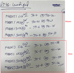
I am trying to make SD card work on the XL2-RM46 launchpad using SPI, and so far I have been able to run the SPI loopback test example using both SPI1 and SPI3. I am able to read the bytes I send on the same SPI using SPITransmitAndReceive function call. However, when I configure SPI1 as master and SPI3 as slave in HALCoGen and transmit on SPI1, followed by a receive on SPI3, I am only able to read 0xFFs. I don't know what I'm missing here. I have tried using both SPI1 and SPI3 as master and the other one as slave by configuring it appropriately in HALCoGen. The SPI1 CS is hooked to the correct CS pin on SPI3, I believe. I am attaching the hcg file with this post.

Weird part is that I am able to probe and observe the data being sent out AND received on the SPI1 MOSI and SPI3 SIMO pins (on an oscilloscope), but reading the data on SPI3 using spiReceiveData still gives me 0xFFs. Is there some other configuration that I am missing?

Link to hcg file: https://drive.google.com/file/d/1DBFMI_IWdv25ezCjZ4Xps28AMqoKYDnf/view?usp=drive_link

Thank you for your time

Sincerely
Karan

  • Hi Karan,

    We have several working and tested SPI and MibSPI examples in below FAQ:

    (+) [FAQ] TMS570LC4357: Examples and Demos available for Hercules Controllers (E.g. TMS570x, RM57x and RM46x etc) - Arm-based microcontrollers forum - Arm-based microcontrollers - TI E2E support forums

    So first i am suggesting you refer them and compare your configurations with them and try to solve the issue on your own. If you face difficulty after referring above examples as well then i will try to solve it.

    --
    Thanks & regards,
    Jagadish.

  • Hi Jagadish

    Thank you for your response.
    I have looked into the introductory videos and am already working off of the 1830. SPI_Master_Test_RM46 example project from the list of example projects since that is the only example for the processor I have. The project, however, uses SPI loopback to test the Transmit and receive functionality on the same SPI (SPI3 in this project) - this works on my launchpad.

    However, I want to have SPI1 as the master and SPI3 as the slave. For the master, I have SPI1 with the same configurations as SPI3 in the example project, and SPI3 as the slave (unchecked master mode in SPI global config), I also have the data formats for both the master and the slave be the same (8 bit Charlen with 300KHz baudrate), with the chip select pin configured as GIO.

    After the module initialization from example code, I do this:

    spiTransmitData(SPI_MASTER, &dataconfig3_t, 6, initiate); // SPI_MASTER is spiREG1
    spiReceiveData(SPI_SLAVE, &s_dataconfig3_t, 6, response); // SPI_SLAVE is spiREG3

    However, the data received on SPI3 is always 0xFF, and not what was in the `initiate` array. Can you please tell me if I am missing any configuration changes to the example project to make this work?
    The only slave examples I could find are for processors other than RM46.

    Thank you for your time

    Sincerely
    Karan

  • Hi Karan,

    I created one example project for your requirement. I am going to attach my example project here, but before that i want to give clarification on few things:

    If you are using master and slave on the same device then polling mode is not possible, i mean you cannot use the spiReceiveData and spiTransmitData functions.

    This is because it is not possible for single core to poll the both the functions right?

    For example:

    If i want to send data from master(SPI1) to the slave(SPI3), that means i should poll the function spiReceiveData on the SPI3 and spiTransmitData  on the SPI1,

    Slave should poll exactly at below condition; it cannot go any further until it receives the data from the master, right?

    If the core polls here, how can it send the data through master using spiTransmitData  function as this function also needs to work in polling mode only.

    The solution for this issue is that, should use the interrupt mode. I mean we should enable the interrupts and use the spiGetData and spiSendData functions.

    Here is my project:

    SPI1_MASTER_SPI3_SLAVE_RM46.zip

    In this example first i am testing master transmit and slave receive:

    For this i am calling the spiGetData function for slave, this will initialize the SPI3_RX_DATA buffer for receiving. Once we initialize the buffer on receiving side, now we can send the data from master using spiSendData function. As you can see now my data properly received on slave side.

    On our next part i am testing slave transmission and master reception:

    For this first i am calling the spiGetData function for master, this will initialize the SPI1_RX_DATA buffer for receiving. And now i am calling the spiSendData function with SPI3_TX_DATA buffer to send the data to the master. But remember that slave cannot initiate any transfer by itself so we should send some dummy bytes from master to receive the data from slave, that is the reason i am calling the spiSendData function with DUMMY_DATA on master.

    Once i did this as you can see, we received the slave data properly on master receive buffer.

    I tested this project on my RM46x Launchpad, as you are using same board right, so you can directly execute it on your board.

    But remember you need to short the below lines of master and slave externally with wires to test this project:

    --
    Thanks & regards,
    Jagadish.

  • Hello Jagadish

    Thank you so much for your response and the example project! This worked perfectly on my launchpad.
    Now I am using your project as base and trying to interact with an external SD card reader which I hooked up to SPI3 module. I made SPI3 master and SPI1 slave and confirmed the working of the example. I changed the `sys_main` file and the changes can be found here: https://drive.google.com/file/d/16aLUUO0fiJKmlO96kPUZVXG1o--lbhv2/view?usp=drive_link

    I followed the SPI SD standard and tried this code on 3 different SD cards, all supporting SPI, and 2 different card holders, but all I am able to read on the master is 0xFF, when I am actually looking for R1 response (0x01). I tried with both [CPOL = 0, CPHA = 0] and [CPOL = 1, CPHA = 1]. Does the SPI module on the launchpad need any additional hardware configuration changes when interacting with external slave devices like the card reader in this case?

    I have tried both interrupt based send and get functions and the blocking transmit and receive functions. Though, in my understanding, both of them should work in this case as we are dealing with an external slave device.

    The following are the wire connections I made (I am using SPI3 as master):

    J11-38 -- CLK
    J11-30 -- CS
    J11-36 -- SO
    J11-37 -- SI

    J5-20 -- GND
    J2-1 -- 3v3

    Using an oscilloscope, I am able to read proper signals on the MOSI and CLK lines, but the MISO line stays high.
    Your help is really appreciated. Thank you again for your time.

    Sincerely
    Karan Pratap

  • Hi Karan Pratap,

    We do have couple of tested SD card example projects for Hercules controllers,

    So, first i am suggesting you refer them because they might be very useful for code implementation:

    (+) TMS570LS3137: I couldn't find the SD Card library for the corresponding MCU. - Arm-based microcontrollers forum - Arm-based microcontrollers - TI E2E support forums

    TMS570LC43x_HDK_SDCard_mibspiDMA « Application - hercules_examples/hercules_examples - Software Examples for Hercules Processors

    --
    Thanks & regards,
    Jagadish.

  • Thank you for all the help. I was able to get SD card working with a few changes to the SPI receive logic. I use the blocking functions (spiTransmitData and spiReceiveData), and keep sending dummy output from master device and sampling the Slave input after sending each byte until it is a valid response (less than 0x80). Within 10 additional dummy clocks, the master is able to sample the correct response.

    Thanks again for all your help Jagadish.

    Sincerely
    Karan Pratap