A related question is a question created from another question. When the related question is created, it will be automatically linked to the original question.
If you have a related question, please click the "Ask a related question" button in the top right corner. The newly created question will be automatically linked to this question.
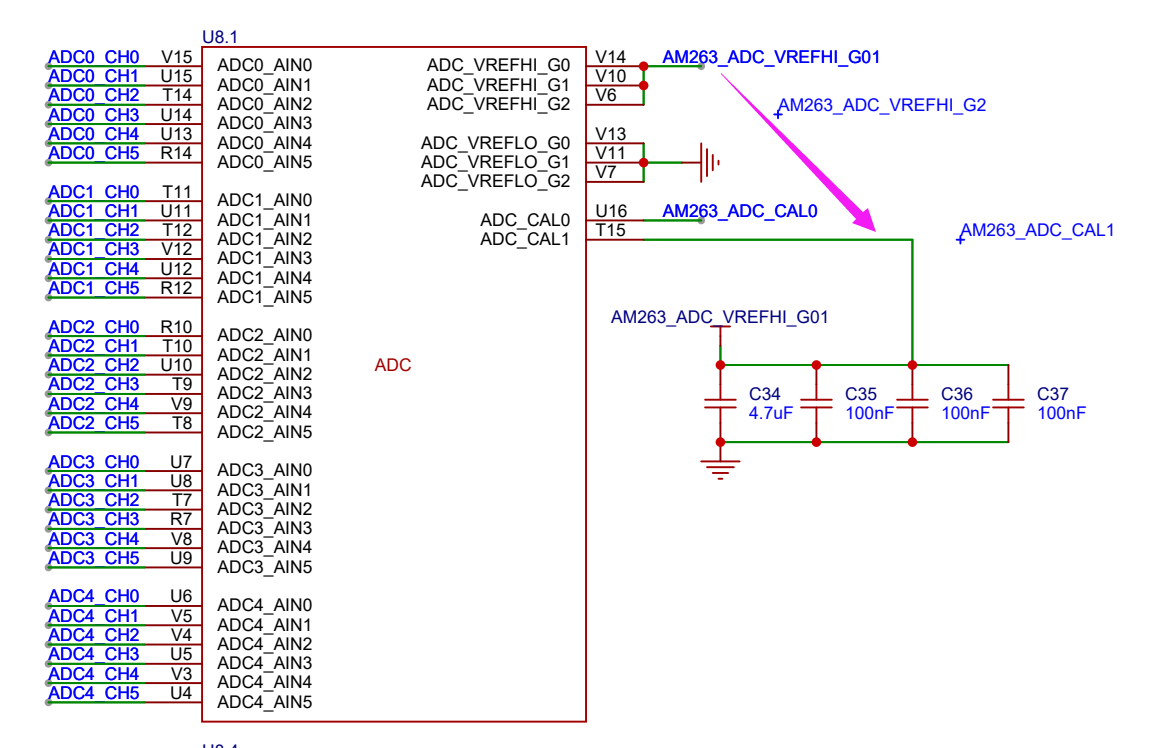
Thank you very much. According to the reference, it can work normally now, but some modifications have been made. I have another question. On my customized board, I use ADC_CAL1 to sample AM263_ADC_VREFHI_G01 (theoretical voltage 1.8V, actual measurement voltage 1.79V), why the ADC value is 2368, and 2368/128*0.1=1.85V instead of 1.8V. I wonder if this is normal.
We reviewed the information internally with the ADC experts who provided the following input:
The concept is understood, using ADC_CAL0 to sample ADCVREF across various ADCs.
However, the ADC is doing a comparison of VIN to VREF. Normally, that would mean that as one changes and the other is fixed (typically VIN and VREF respectively, but the opposite would work too), you'll get a different code.
If VIN *is* VREF, then we believe you'll just get the same result regardless of what the actual value of VREF is.
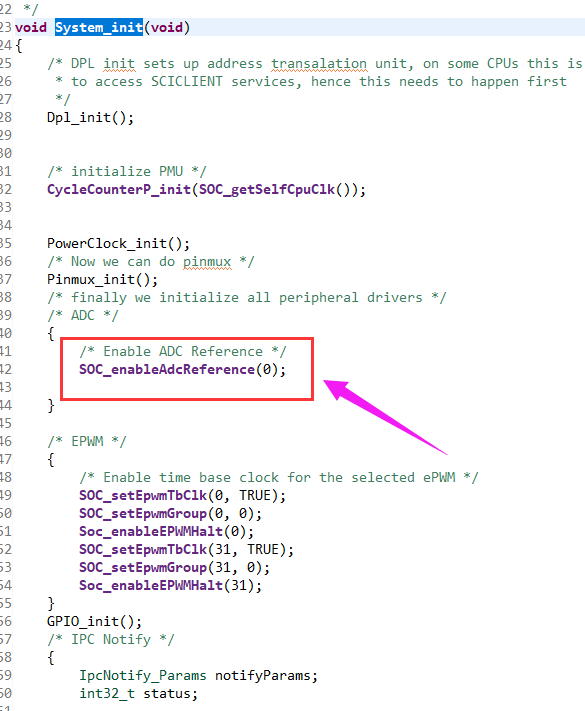
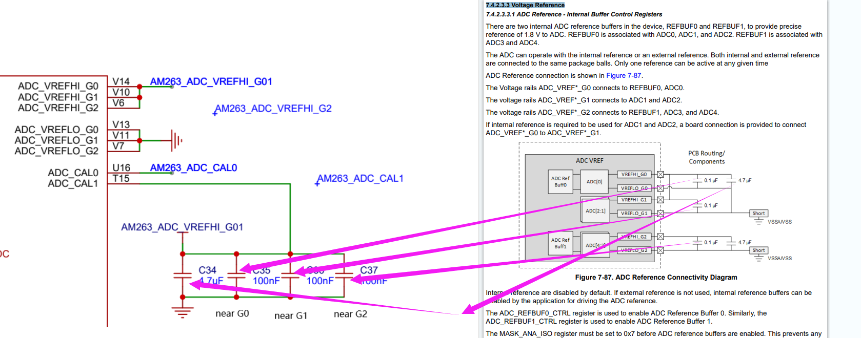
The schematic screenshot you shared shows an invalid ADC_VREF configuration. Please refer to the device TRM chapter (7.4.2.3.3 Voltage Reference).
This is likely contributing to your inaccurate/noisy ADC readings.
Please follow the guidelines provided in the TRM for the ADC voltage reference and let us know if the issue persists.
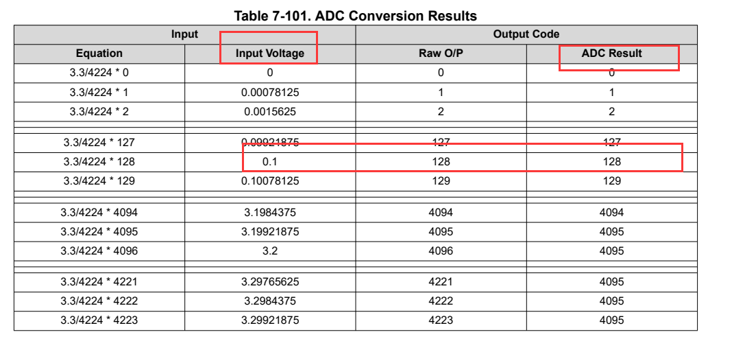
Hello expert, I know this is not an efficient ADC connection because sampling the VREF will get the same value every time, but my question is why this value is different from the theoretical value. As mentioned above and shown in the table, the theoretical value of the sampled Vref should always be 2304, but the actual result is 2368, the error is so large that I can't find the reason. Thank you very much.
As mentioned above, I believe that the discrepancy you are seeing is due to an invalid hardware setup for the ADC reference voltage. The accuracy of the ADC readings is directly dependent on a stable valid VREF voltage. I believe if you make the changes to your VREF circuit as recommended in the TRM, this discrepancy will resolve itself. If your VREF isn't accurate and stable, your ADC readings will also be inaccurate and unstable.
Hello, Zackary Fleenor The two hardware is basically consistent, the corresponding relationship is shown in the figure, the capacitor is placed close to the chip pin. The lack of a 4.7uf capacitor is because I will only turn on one of the ADC REF buff0 or buff1, or I will not turn on the internal ref buff and will use the ref2030 and op amp to produce a 1.8V reference, in all three cases the converted value is 2368 instead of 2304. This is very strange. The second problem is that I don't know how the chip internally changes the 1.8V reference source into the 3.3V reference source required by the internal ADC quantizer, and whether the inaccurate ADC values have anything to do with this - can the experts sample the REF using the ADC to see what the converted value is actually?
Thank you for providing this additional info. I am working with the Analog Design team internally to get more feedback to you. I will work on getting a similar test running so we can check on our side for similar results.
We attempted to replicate the issue on our side with some simulation tools and end up with the expected result of 2304. Can you provide us with the exact ADC SW configuration you are using? Have you made any changes from the default device settings?
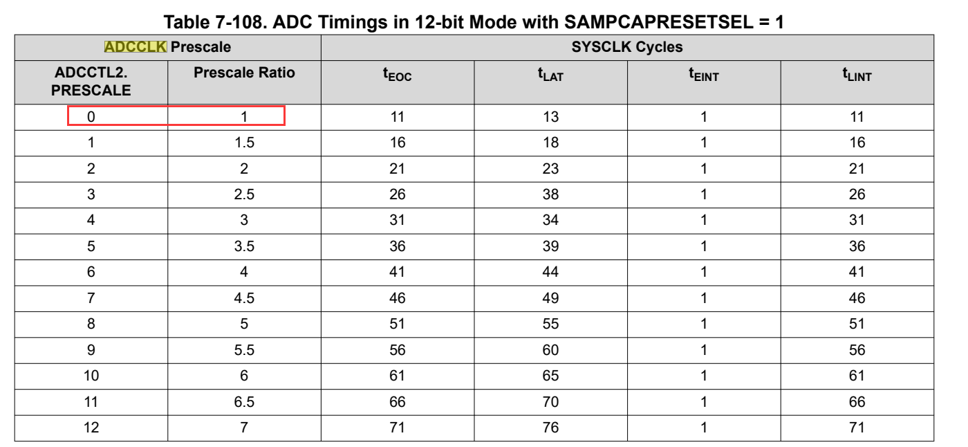
Thanks for your reminding, I have found the problem, but I don't quite understand the reason. I added the ADC directly using syscfg, but the default configuration option for "ADC Clock Prescaler" in syscfg is "/1", which makes the ADC conversion result incorrect. The configuration used in demo is "/3", and the conversion result is correct. However, it is shown in TRM that "/1" can be configured, and there is no limit to ADCCLK found in the data sheet. Therefore, the question is whether ADCCLK is too high and what is the maximum flat frequency of ADCCLK. My attempt to convert" /2" (100MHz) is also normal. Thanks again ~
So glad to hear you were able to resolve the issue. The official maximum operating frequency for ADC_CLK is 66.667 MHz which is why all the examples utilize the /3 divider configuration. This parameter is planned to be included in the next datasheet release.